• Product
  • Suppliers
  • Manufacturers
  • Solutions
  • Free tools
  • Knowledges
  • Experts
  • Communities
Search


Optical Modulation

Encyclopedia
Encyclopedia
Field: Encyclopedia
0
China

Definition of Optical Modulation

Optical modulation refers to the process of altering a light wave in accordance with a high - frequency electrical signal that carries information. The modified light waves are subsequently transmitted either through a transparent medium or via an optical fiber cable.

More precisely, optical modulation can be defined as the conversion of an information - laden electrical signal into a corresponding light signal. This transformation enables the efficient transmission of data over long distances with high fidelity.

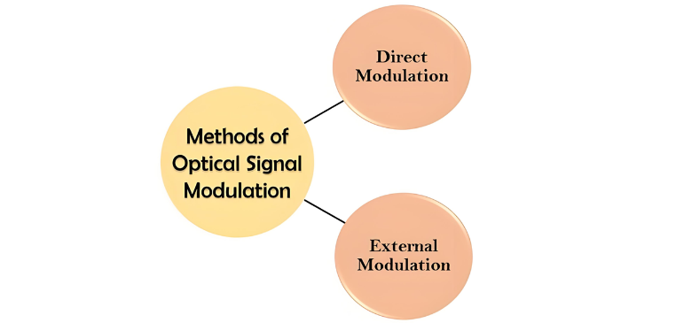
Fundamentally, there are two distinct approaches to modulating optical signals, which are categorized as follows:

image.png

Direct Modulation

As the name implies, direct modulation is a technique where the information intended for transmission is directly superimposed onto the light stream emitted by the source. In this approach, the driving current of the light source, typically a laser, is directly varied in accordance with the electrical information signal. This direct alteration of the current generates a corresponding change in the optical power signal, eliminating the need for separate optical modulators to modulate the optical signal.

However, this modulation technique has significant drawbacks. These are mainly related to the carrier lifetimes of spontaneous and stimulated emission, as well as the photon lifetime of the light source. When using a laser transmitter for direct modulation, the laser switches on and off in response to the electrical signal or driving current. During this process, the laser linewidth tends to broaden, a phenomenon known as chirp. This broadening of the laser linewidth severely limits the application of direct modulation, making it unsuitable for data rates exceeding 2.5 Gbps.

External Modulation

In contrast, external modulation employs dedicated optical modulators to modify optical signals and alter their characteristics. This technique is particularly well - suited for modulating signals with data rates exceeding 10 Gbps. While it excels at handling high - speed data, there is no strict requirement to use external modulation solely for high - data - rate signals; it can be applied in other scenarios as well.

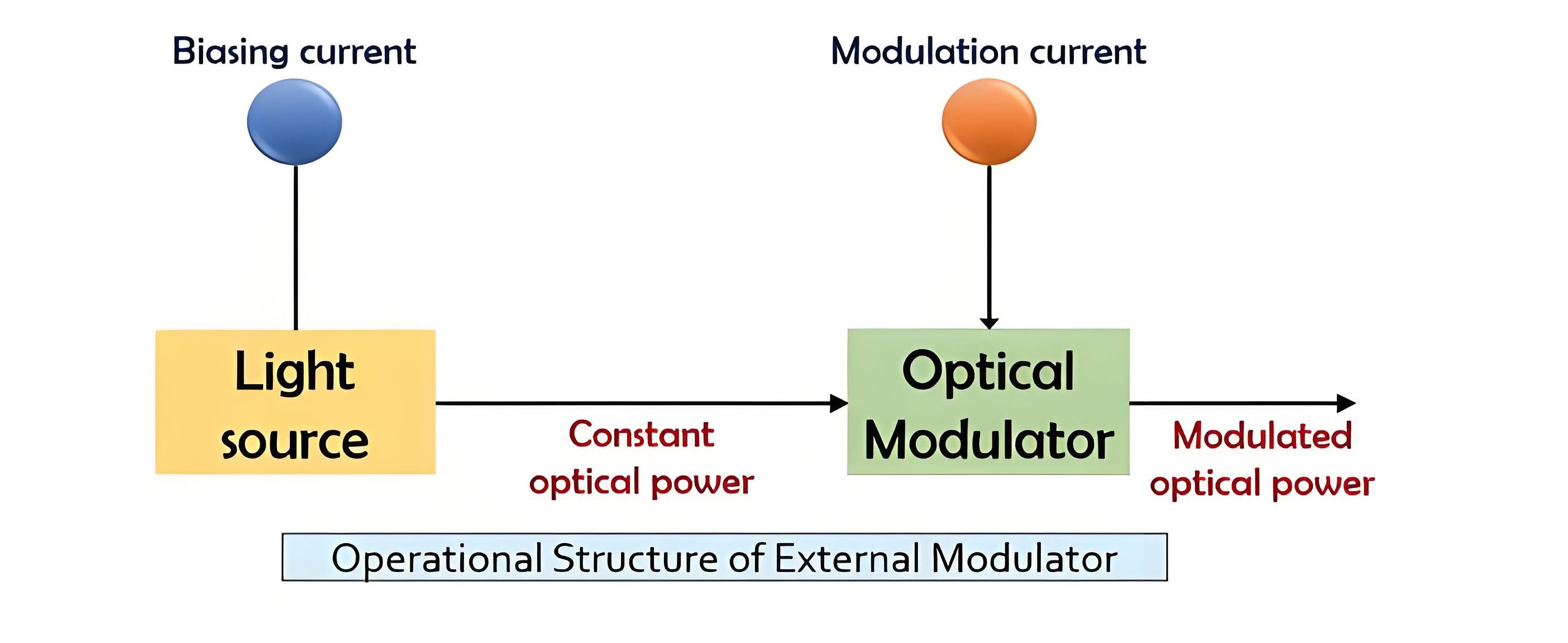
The following figure illustrates the operational mechanism of an external modulator, highlighting how it interacts with the optical signal to achieve the desired modulation.

Optical Modulation.jpg

External Modulation Details

In the external modulation setup, the first component is the light source, typically a laser diode. Following the laser diode, an optical modulator circuit comes into play. This circuit modifies the light wave emitted by the source in accordance with the incoming electrical signal.

The laser diode generates an optical signal with a constant amplitude. Consequently, instead of altering the amplitude of the optical signal, the electrical signal influences the power level of the optical output. As a result, at the output of the modulator, a time - varying optical signal is produced, effectively carrying the information encoded in the electrical input.

It's important to note that the circuitry of the external modulator can be designed in two ways. It can be integrated with the optical source, creating a more compact and streamlined solution. Alternatively, it can function as a separate, stand - alone device, offering flexibility in system design and integration.

Optical modulators, which are central to the external modulation process, can be broadly classified into two main types:

Electro - Optical Phase Modulator

Also known as the Mach - Zehnder Modulator, this type of optical modulator is primarily constructed using lithium niobate as its fundamental material. The unique properties of lithium niobate enable precise manipulation of the optical signal based on electrical inputs. The following figure illustrates the operational mechanism of an electro - optical external modulator, detailing how it modifies the optical signal through the interaction between electrical and optical components.

image.png

Electro - Optical Phase Modulator Operation

In the electro - optical phase modulator, a beam splitter and a beam combiner play crucial roles in manipulating light waves. When an optical signal enters the modulator, the beam splitter divides the light beam into two equal parts, directing each half along a distinct path. Subsequently, an applied electric signal alters the phase of the light beam traveling through one of these paths.

After traversing their respective routes, the two light waves reach the beam combiner, where they recombine. This recombination can occur in two ways: constructively or destructively. When constructive recombination takes place, the combined light waves reinforce each other, resulting in a bright light wave at the modulator's output, as represented by pulse 1. Conversely, during destructive recombination, the two halves of the light beam cancel each other out, leading to no light signal being detected at the output, which is indicated by pulse 0.

Electro - Absorption Modulator

The electro - absorption modulator is primarily fabricated from indium phosphide. In this type of modulator, the electrical signal carrying information modifies the properties of the material through which light propagates. Depending on these property changes, either pulse 1 or 0 is generated at the output.

Notably, the electro - absorption modulator can be integrated with a laser diode and enclosed within a standard butterfly package. This integrated design offers significant advantages. By combining the modulator and laser diode into a single unit, it reduces the overall space requirements of the device. Additionally, it optimizes power consumption and lowers voltage demands compared to using a separate laser source and modulator circuit, making it a more compact, efficient, and practical solution for various optical communication applications.

Give a tip and encourage the author!
Recommended
Composition and Working Principle of Photovoltaic Power Generation Systems
Composition and Working Principle of Photovoltaic (PV) Power Generation SystemsA photovoltaic (PV) power generation system is primarily composed of PV modules, a controller, an inverter, batteries, and other accessories (batteries are not required for grid-connected systems). Based on whether it relies on the public power grid, PV systems are divided into off-grid and grid-connected types. Off-grid systems operate independently without relying on the utility grid. They are equipped with energy-s
Encyclopedia
10/09/2025
How to Maintain a PV Plant? State Grid Answers 8 Common O&M Questions(2)
1. On a scorching sunny day, do damaged vulnerable components need to be replaced immediately?Immediate replacement is not recommended. If replacement is necessary, it is advisable to do so in the early morning or late afternoon. You should contact the power station’s operation and maintenance (O&M) personnel promptly, and have professional staff go to the site for replacement.2. To prevent photovoltaic (PV) modules from being hit by heavy objects, can wire mesh protective screens be install
Encyclopedia
09/06/2025
How to Maintain a PV Plant? State Grid Answers 8 Common O&M Questions(1)
1. What are the common faults of distributed photovoltaic (PV) power generation systems? What typical problems may occur in various components of the system?Common faults include inverters failing to operate or start due to voltage not reaching the startup set value, and low power generation caused by issues with PV modules or inverters. Typical problems that may occur in system components are burnout of junction boxes and local burnout of PV modules.2. How to handle common faults of distributed
Leon
09/06/2025
Short Circuit vs. Overload: Understanding the Differences and How to Protect Your Power System
One of the main differences between a short circuit and an overload is that a short circuit occurs due to a fault between conductors (line-to-line) or between a conductor and earth (line-to-ground), whereas an overload refers to a situation where equipment draws more current than its rated capacity from the power supply.Other key differences between the two are explained in the comparison chart below.The term "overload" typically refers to a condition in a circuit or connected device. A circuit
Edwiin
08/28/2025
Send inquiry
Download
Get the IEE Business Application
Use the IEE-Business app to find equipment, obtain solutions, connect with experts, and participate in industry collaboration anytime, anywhere—fully supporting the development of your power projects and business.