• Product
  • Suppliers
  • Manufacturers
  • Solutions
  • Free tools
  • Knowledges
  • Experts
  • Communities
Search


What are the uses of impedance, power factor and phase Angle in alternating current? What is the relationship between these factors?

Encyclopedia
Encyclopedia
Field: Encyclopedia
0
China

The role and relation of impedance, power factor and phase Angle in alternating current


In the analysis of AC circuits, impedance, power factor and phase Angle are three basic concepts, each of which has a specific purpose and a close relationship with each other.


Impedance


Impedance is a comprehensive parameter that describes the resistance, inductance and capacitance of the AC circuit to hinder the current flow. It consists of resistance (R), inductive reactance (XL), and capacitive reactance (XC), but is not simply added together, but rather their sum on the vector 2. The unit of impedance is ohm (Ω), and the size of the impedance is related to the frequency in the circuit, the higher the frequency, the smaller the capacitive reactance, the greater the inductive reactance; And vice versa. The value of the impedance changes with frequency, which is crucial for understanding and designing AC circuits.


Power factor


The power factor is the ratio of the active power (P) to the apparent power (S) in an AC circuit, usually expressed as cosφ. The power factor reflects the ratio of the actual power consumed in a circuit to the maximum power that the circuit can provide. Ideally, the power factor is 1, indicating that the circuit is perfectly matched and there is no reactive power loss. When the value is lower than 1, it indicates the loss of reactive power and reduces the efficiency of the grid. The power factor Angle (φ) is the inverse tangent of the power factor cosφ, usually between -90 degrees and +90 degrees, indicating the phase difference between current and voltage.


Phase Angle


The phase Angle is the phase difference between the voltage and current waveforms, usually denoted by θ. In an AC circuit, both voltage and current are sinusoidal waveforms, and the phase difference determines the energy flow in the circuit. When the voltage and current are in phase, the phase difference is 0 degrees, and the power is maximum. When the voltage leads the current by 90 degrees or lags by 90 degrees, it corresponds to reactive power and inductive load or capacitive load, respectively. The impedance Angle (φ) is actually the power factor Angle, which is the Angle difference between the voltage and the current phasor, and for impedance components (such as resistors, inductors and capacitors), the impedance Angle is equal to the power factor Angle.


Relationship summary


There are the following relationships between impedance, power factor and phase Angle:


Impedance (Z) is the complex amount of voltage and current in the circuit, including the vector sum of resistance, inductive reactance and capacitive reactance, reflecting the total obstruction of the circuit to the current.


The power factor (cosφ) is the cosine value of the impedance Angle, indicating the ratio of active power to apparent power, reflecting the efficiency of the circuit.


The phase Angle (θ or φ) is the phase difference between the voltage and current waveform, which determines the energy flow of the circuit and is the specific embodiment of the power factor Angle.


Understanding these concepts helps to analyze and optimize AC circuit design, improve energy efficiency and reduce reactive power loss.


Give a tip and encourage the author!
Recommended
Composition and Working Principle of Photovoltaic Power Generation Systems
Composition and Working Principle of Photovoltaic (PV) Power Generation SystemsA photovoltaic (PV) power generation system is primarily composed of PV modules, a controller, an inverter, batteries, and other accessories (batteries are not required for grid-connected systems). Based on whether it relies on the public power grid, PV systems are divided into off-grid and grid-connected types. Off-grid systems operate independently without relying on the utility grid. They are equipped with energy-s
Encyclopedia
10/09/2025
How to Maintain a PV Plant? State Grid Answers 8 Common O&M Questions(2)
1. On a scorching sunny day, do damaged vulnerable components need to be replaced immediately?Immediate replacement is not recommended. If replacement is necessary, it is advisable to do so in the early morning or late afternoon. You should contact the power station’s operation and maintenance (O&M) personnel promptly, and have professional staff go to the site for replacement.2. To prevent photovoltaic (PV) modules from being hit by heavy objects, can wire mesh protective screens be install
Encyclopedia
09/06/2025
How to Maintain a PV Plant? State Grid Answers 8 Common O&M Questions(1)
1. What are the common faults of distributed photovoltaic (PV) power generation systems? What typical problems may occur in various components of the system?Common faults include inverters failing to operate or start due to voltage not reaching the startup set value, and low power generation caused by issues with PV modules or inverters. Typical problems that may occur in system components are burnout of junction boxes and local burnout of PV modules.2. How to handle common faults of distributed
Leon
09/06/2025
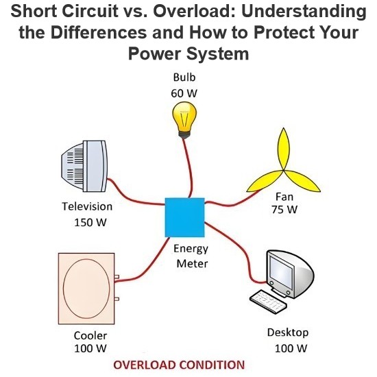
Short Circuit vs. Overload: Understanding the Differences and How to Protect Your Power System
One of the main differences between a short circuit and an overload is that a short circuit occurs due to a fault between conductors (line-to-line) or between a conductor and earth (line-to-ground), whereas an overload refers to a situation where equipment draws more current than its rated capacity from the power supply.Other key differences between the two are explained in the comparison chart below.The term "overload" typically refers to a condition in a circuit or connected device. A circuit
Edwiin
08/28/2025
Send inquiry
Download
Get the IEE Business Application
Use the IEE-Business app to find equipment, obtain solutions, connect with experts, and participate in industry collaboration anytime, anywhere—fully supporting the development of your power projects and business.