Fleming’s Left And Right Hand Thumb Rules Explained

Electrical4u
03/13/2024

What are Fleming’s Left And Right Hand Rules?

Whenever a current carrying conductor comes under a magnetic field, there will be a force acting on the conductor. The direction of this force can be found using Fleming’s Left Hand Rule (also known as ‘Flemings left-hand rule for motors’).

Similarly if a conductor is forcefully brought under a magnetic field, there will be an induced current in that conductor. The direction of this force can be found using Fleming’s Right Hand Rule.

In both Fleming’s left and right hand rules, there is a relation between the magnetic field, the current, and force. This relation is directionally determined by Fleming’s left hand rule and Fleming’s right hand rule respectively.

These rules do not determine the magnitude but instead show the direction of any of the three parameters (magnetic field, current, force) when the direction of the other two parameters is known.

Fleming’s Left-Hand rule is mainly applicable to electric motors and Fleming’s Right-Hand rule is mainly applicable to electric generators.

What is Fleming’s Left Hand Rule?

It is found that whenever a current carrying conductor is placed inside a magnetic field, a force acts on the conductor, in a direction perpendicular to both the directions of the current and the magnetic field.

Fleming's Left Hand Rule

In the figure below, a portion of a conductor of length ‘L’ is placed vertically in a uniform horizontal magnetic field of strength ‘H’, produced by two magnetic poles N and S. If the current ‘I’ is flowing through this conductor, the magnitude of the force acting on the conductor is:

Left Hand Rule Magnetic Field

Hold out your left hand with the forefinger, second finger and thumb at the right angle to one another. If the forefinger represents the direction of the field and the second finger represents that of the current, then thumb gives the direction of the force.

While current flows through a conductor, one magnetic field is induced around it. The magnetic field can be imagined by considering numbers of closed magnetic lines of force around the conductor.

The direction of magnetic lines of force can be determined by Maxwell’s corkscrew rule or right-hand grip rule.

As per these rules, the direction of the magnetic lines of force (or flux lines) is clockwise if the current is flowing away from the viewer, that is if the direction of current through the conductor is inward from the reference plane as shown in the figure.

Rule Hand Rule Magnetic Field


Now if a horizontal magnetic field is applied externally to the conductor, these two magnetic fields i.e. field around the conductor due to the current through it and the externally applied field will interact with each other.

We observe in the picture that the magnetic lines of force of external magnetic field are from N to S pole that is from left to right.

The magnetic lines of force of external magnetic field and magnetic lines of force due to the current in the conductor are in the same direction above the conductor, and they are in the opposite direction below the conductor.

Hence there will be larger numbers of co-directional magnetic lines of force above the conductor than that of below the conductor.

Consequently, there will be a larger concentration of magnetic lines of force in a small space above the conductor. As magnetic lines of force are no longer straight lines, they are under tension like stretched rubber bands.

Rule Hand Rule Magnetic Force

As a result, there will be a force which will tend to move the conductor from the more concentrated magnetic field to less concentrated magnetic field, that is from the present position to downwards.

Now if you observe the direction of the current, force and magnetic field in the above explanation, you will find that the directions are according to the Fleming left-hand rule.

What is Fleming’s Right Hand Rule?

As per Faraday’s law of electromagnetic induction, whenever a conductor moves inside a magnetic field, there will be an induced current in it. If this conductor gets forcefully moved inside the magnetic field, there will be a relation between the direction of applied force, magnetic field and the current.

This relation among these three directions is determined by Fleming’s right-hand Rule.

Fleming’s right hand rule

This rule states “Hold out the right hand with the first finger, second finger and thumb at the right angle to each other. If forefinger represents the direction of the line of force, the thumb points in the direction of motion or applied force, then second finger points in the direction of the induced current”.

Who Invented The Left and Right Hand Thumb Rules?

The left and right hand thumb rules were founded by John Ambrose Fleming in the late 19th century.

John discovered both of these rules and named them after himself. The rules are now well known as Fleming’s left and right-hand rule.

John Ambrose Fleming

Statement: Respect the original, good articles worth sharing, if there is infringement please contact delete.

Electrical4u

Electrical4U is dedicated to the teaching and sharing of all things related to electrical and electronics engineering.

What is a Pure Resistive AC Circuit?
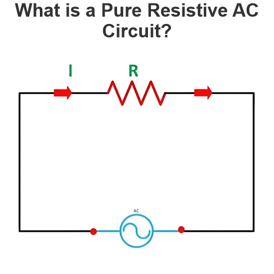
Pure Resistive AC CircuitA circuit containing only a pure resistanceR(in ohms) in an AC system is defined as a Pure Resistive AC Circuit, devoid of inductance and capacitance. Alternating current and voltage in such a circuit oscillate bidirectionally, generating a sine wave (sinusoidal waveform). In this configuration, power is dissipated by the resistor, with voltage and current in perfect phase—both reaching their peak values simultaneously. As a passive component, the resistor neither
Edwiin
06/02/2025
What is a Pure Capacitor Circuit?
Pure Capacitor CircuitA circuit comprising only a pure capacitor with capacitanceC(measured in farads) is termed a Pure Capacitor Circuit. Capacitors store electrical energy within an electric field, a characteristic known ascapacitance(alternatively referred to as a "condenser"). Structurally, a capacitor consists of two conductive plates separated by a dielectric medium—common dielectric materials include glass, paper, mica, and oxide layers. In an ideal AC capacitor circuit, the current
Edwiin
06/02/2025
Resistance Switching in a Circuit Breaker
Resistance SwitchingResistance switching refers to the practice of connecting a fixed resistor in parallel with the contact gap or arc of a circuit breaker. This technique is applied in circuit breakers with high post-arc resistance in the contact space, primarily to mitigate re-striking voltages and transient voltage surges.Severe voltage fluctuations in power systems arise from two main scenarios: interrupting low-magnitude inductive currents and breaking capacitive currents. Such overvoltages
Edwiin
05/23/2025
What is Biot Savart Law?
The Biot-Savart Law is employed to determine the magnetic field intensity dHnear a current-carrying conductor. In other words, it describes the relationship between the magnetic field intensity generated by a source current element. This law was formulated in 1820 by Jean-Baptiste Biot and Félix Savart. For a straight wire, the direction of the magnetic field adheres to the right-hand rule. The Biot-Savart Law is also referred to as Laplace’s law or Ampère’s law.Conside
Edwiin
05/20/2025
Inquiry
Download
IEE-Business is dedicated to serving the personnel in the global power industry.
Join IEE-Business, not only can you discover power equipment and power knowledge, but also canhnd like - minded friends!