Watts Law: What is it? Formula, Examples & Watt’s Law Triangle

Electrical4u
03/13/2024

What is Watts Law?

Watt’s law defines the relationship between power, amperage, and voltage drop in an electrical circuit. Watts Law also states that the power of an electrical circuit is the product of its voltage and current.

Watts Law Formula

The formula for Watts law can be given as follows. It gives the relationships between power (watts), current (amps) and voltage(volt)


\begin{align*} Power = Voltage\times Current\end{align*}


\begin{align*}Voltage = \frac{Power}{Current} \end{align*}

\begin{align*}Current = \frac{Power}{Voltage} \end{align*}

Watts Law Example 1

Suppose you were trying to find out how many 500-watt lighting devices you could plug into a circuit without blowing a fuse.

First, you’d like to know how much current can be drawn from the circuit. Most homes have 15A circuits and most of the circuits have a circuit breaker off of 20A. So, what would be the total power?

We know that Watts = Volts x Amps. So, here voltage and current values are given as 110V and 20A. Now, the calculated Watts would be 2200W. So whatever we plug into our circuit must be less than 2200 watts, since that’s all the power available on this circuit. You could safely plug four 500-watt lights into the circuit (or two 1000watt lights) with a 200 Watt as a safety margin.

Watts Law Example 2

If the light bulb voltage is 120 volts and the power is 60 watts, what really is the current?

So, here the voltage and power of a bulb are given as 120V and 60W respectively. We already know current = Power / Voltage. So, on substituting the values, the value of current would be 0.5 Amperes.

Watts Law Example 3

Consider your home’s 100 Watt light bulb. We know that the voltage applied to the bulb is usually 110V or 220V so that the current consumed can be measured as follows.

I = P/V = 100W / 110V = 0.91 Amps or I = P/V = 100W / 220V = 0.45 Amps.

But you can see that it’s easier to use a 60W light bulb. Your electrical provider would usually bill you for use in Kilo-Watt Hours (kWh). One kWh is the amount of energy required to do 1000 watts of energy for one hour.

Watts Law Vs. Ohms Law

Watt’s Law says the relationship between power, voltage and current.

Power: Power is the rate at which energy is being used. The unit of measurement for electrical power is called the Watt, named after James Watt. Whenever one Volt is used to move an Ampere through a circuit, the work done is equal to one Watt of power.


\begin{align*} P = V \times I\end{align*}

As electrons pass across a resistance in an electrical circuit, the electrons collide with each other and the atoms that make up the resistance. These collisions produce heat and result in a loss of energy. Hence a variation in watts law is given as


\begin{align*}P = I^{2}R\end{align*}

Current: The movement of electrons or other particles through a conductor is known as current. The unit used to calculate the current parameter is the Ampere. The symbol used to represent the amplifier is the letter “A.” The upper and lower cases are used depending on the situation. The symbol used to represent the current parameter is the letter “I.”

Voltage: The electrical pressure that causes electrons or other particles to move through a circuit is known as Voltage. The unit used to calculate the voltage parameter is the volt. The symbol used to represent the volt is the letter “V.” Both the upper case and the lower case are used depending on the situation.

Resistance: It is a measure of the resistance to the current flow in the electrical circuit. Resistance is measured by ohms, symbolised by the Greek letter omega. Resistance is also good because it gives us a way to shield ourselves from the harmful energy of electricity.

Ohm’s Law affirms the relationship between voltage, current and resistance.

The Ohm’s law can be represented as:


\begin{align*} V = I \times R \end{align*}


\begin{align*}I = V/R \end{align*}


\begin{align*}R = V/I \end{align*}Ohms Law Pie Chart


Ohms Law Pie Chart


Watts Law Triangle

Since both laws use the same electrical quantities, they can be combined to come up with some useful equations. The basic Ohms Law equation is transposed for power. It gives us some combinations of the same equation to find the various individual quantities.

Power Triangle


Power Triangle


There are three possible formulas for calculating electrical power in a circuit. If the calculated power is positive, it means the equipment is consuming or using power. But if the calculated power is negative in value the component produces or generates power.

Power Triangle Values


Values calculated from Power Triangle


Applications of Watts law

Some of the applications of Watt’s law include:

  • If you have a power source, you would use this formula to measure the actual power which the source can produce. You could use it to measure the power requirement for just one component. When the current and the voltage of the source are given, the values can be multiplied.

  • The power requirement of a building can be measured using the Watt formula. It is important to estimate the total power requirement when designing the wiring of a building. You can then use this knowledge to decide the appropriate wire sizes for the house. You may also measure the cost of electricity. The power requirement of the building is accomplished by measuring and adding up the individual power rating of each electrical device or part of the building.

  • If you know the power and voltage of the electrical component, you can measure the current using the Watt formula (I = P / V). The same is true for voltage when only current and power (V = P / I) are understood.

  • The formulas obtained from the combination of Watt’s law and Ohm’s law can be applied to determine the electrical resistance of a component.


Statement: Respect the original, good articles worth sharing, if there is infringement please contact delete.


Electrical4u

Electrical4U is dedicated to the teaching and sharing of all things related to electrical and electronics engineering.

What is a Pure Resistive AC Circuit?
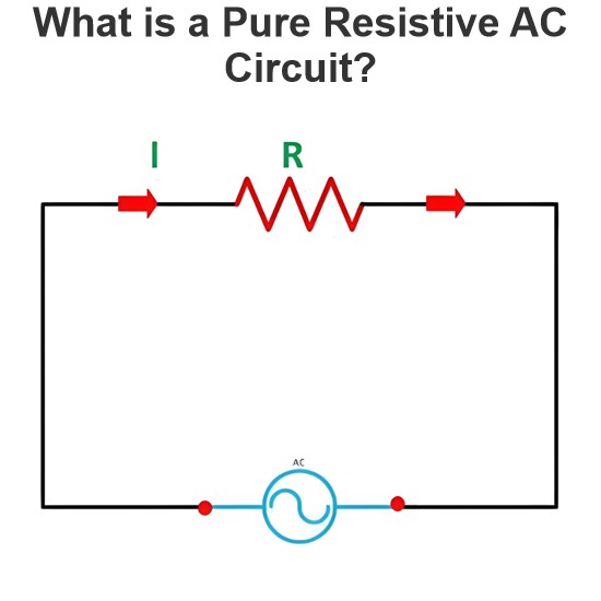
Pure Resistive AC CircuitA circuit containing only a pure resistanceR(in ohms) in an AC system is defined as a Pure Resistive AC Circuit, devoid of inductance and capacitance. Alternating current and voltage in such a circuit oscillate bidirectionally, generating a sine wave (sinusoidal waveform). In this configuration, power is dissipated by the resistor, with voltage and current in perfect phase—both reaching their peak values simultaneously. As a passive component, the resistor neither
Edwiin
06/02/2025
What is a Pure Capacitor Circuit?
Pure Capacitor CircuitA circuit comprising only a pure capacitor with capacitanceC(measured in farads) is termed a Pure Capacitor Circuit. Capacitors store electrical energy within an electric field, a characteristic known ascapacitance(alternatively referred to as a "condenser"). Structurally, a capacitor consists of two conductive plates separated by a dielectric medium—common dielectric materials include glass, paper, mica, and oxide layers. In an ideal AC capacitor circuit, the current
Edwiin
06/02/2025
Resistance Switching in a Circuit Breaker
Resistance SwitchingResistance switching refers to the practice of connecting a fixed resistor in parallel with the contact gap or arc of a circuit breaker. This technique is applied in circuit breakers with high post-arc resistance in the contact space, primarily to mitigate re-striking voltages and transient voltage surges.Severe voltage fluctuations in power systems arise from two main scenarios: interrupting low-magnitude inductive currents and breaking capacitive currents. Such overvoltages
Edwiin
05/23/2025
What is Biot Savart Law?
The Biot-Savart Law is employed to determine the magnetic field intensity dHnear a current-carrying conductor. In other words, it describes the relationship between the magnetic field intensity generated by a source current element. This law was formulated in 1820 by Jean-Baptiste Biot and Félix Savart. For a straight wire, the direction of the magnetic field adheres to the right-hand rule. The Biot-Savart Law is also referred to as Laplace’s law or Ampère’s law.Conside
Edwiin
05/20/2025
Inquiry
Download
IEE-Business is dedicated to serving the personnel in the global power industry.
Join IEE-Business, not only can you discover power equipment and power knowledge, but also canhnd like - minded friends!