Capacitance in Series

The Electricity Forum
03/16/2024

When working with individual capacitors in electronic circuits, it is essential to understand their behaviour and effects. For example, in a series arrangement, the positive plate of one capacitor is connected to the negative plate of the next capacitor in line. This unique connection impacts the circuit's total equivalent capacitance (C_total), causing the total capacitance to be smaller than the smallest individual capacitance (C) present in the series.

A series circuit is characterized by its linear sequence of components, through which the current flows in a single path. In such circuits, the total voltage is distributed across each component in proportion to its resistance. The overall resistance of a series circuit is equal to the sum of the individual resistances of the connected components.

When they are connected in series, the total capacitance of the circuit is affected. This is because the positive plate of capacitors is connected in series to the total capacitance. Each capacitor stores the same charge in this arrangement, and the total voltage is divided across the capacitors in proportion to their capacitance. This characteristic of series-connected capacitors plays a significant role in designing electronic circuits that require specific voltage and charge distribution properties.

Formula for Calculation

To accurately calculate the total capacitance of capacitors connected in series, the following formula is employed:

C_total = 1 / (1/C1 + 1/C2 + 1/C3 + ... + 1/Cn)

This formula calculates the inverse of the total capacitance. To find the actual total capacitance, take the inverse of the sum of the inverse individual capacitances. This mathematical process allows for a precise determination of the overall capacitance value in the series configuration, which is crucial when designing or analyzing electronic circuits.


Impact of the Smallest Capacitor on Total Capacitance

When several are connected in series, the total capacitance becomes smaller than the smallest individual capacitance. This phenomenon occurs because the capacitor with a smaller capacitance limits the total capacitance, acting as a bottleneck for the current flow and restricting the total charge stored in the circuit. Understanding this limiting effect is critical when selecting capacitors for a series configuration, as the smallest capacitor will significantly impact the overall performance of the electronic circuit.


Comparing Capacitors in Parallel and Series Configurations

In contrast to capacitors in series, when capacitors are connected in parallel, the total capacitance is the sum of the individual capacitances. This difference occurs because each capacitor is directly connected to the power source in a parallel circuit, allowing it to store its charge independently. Consequently, capacitors in parallel configurations offer higher overall capacitance values, making them suitable for applications that require increased charge storage capabilities.

Equivalent Capacitance and Voltage Drop in Series Capacitors

The equivalent capacitance of capacitors connected in series can be determined by dividing the total charge stored in the circuit by the total voltage across the circuit. This is because the total charge stored in the circuit equals the sum of the charges on each capacitor. In contrast, the total voltage is equal to calculate the total capacitance for the number of capacitors connected.

The voltage drop in capacitors connected in series is divided among the capacitors in proportion to their capacitance. This means that the voltage across each capacitor is proportional to its capacitance. Understanding the voltage drop distribution in series capacitors is essential when designing circuits that rely on specific voltage levels across components.


Replacing Capacitors in Series with a Single Equivalent Capacitor and Combination Circuits

In some cases, capacitors in series can be replaced with a single equivalent capacitor that has the same capacitance value as the equivalent capacitance of the capacitors in series. This replacement technique can simplify circuit design and analysis, consolidating multiple components into a single element with equivalent electrical properties.

In a combination circuit, capacitors are connected in both series and parallel configurations. These complex arrangements are commonly found in practical electronic applications, as they offer more flexibility and adaptability in achieving desired circuit properties. To calculate the total capacitance of a combination circuit, first, compute the capacitance of each series combination, then add those capacitances to find the total capacitance. This process might involve several steps, as the designer needs to consider both the series and parallel components' contributions to the overall capacitance value.

Applications and Considerations of Capacitors in Series

Capacitors in series configurations are utilized in various electronic applications, such as power supply filtering, signal coupling, and decoupling, as well as in tuning and timing circuits. When designing these applications, engineers must consider the capacitors' voltage ratings, tolerances, temperature coefficients, and other parameters to ensure the circuit functions as desired.

One crucial consideration when working with capacitors in series is the voltage rating. The voltage rating of each capacitor must be sufficient to handle the voltage that will be applied across it. Since the total voltage is distributed among the capacitors in series, selecting capacitors with appropriate voltage ratings is essential to prevent component failure or degradation.

Another important consideration is the capacitors' tolerances, which indicate the possible variation in capacitance values from their nominal specifications. Capacitors with tighter tolerances may be required for precise applications, as variations in capacitance values can impact the overall performance of the electronic circuit.

Statement: Respect the original, good articles worth sharing, if there is infringement please contact delete.

The Electricity Forum

Electricity Forum publishes Electricity Today T&D Magazine and Intelligent Power Today Industrial Electrical Magazine. We publish electrical technical handbooks and associated digital magazine advertising supplements.

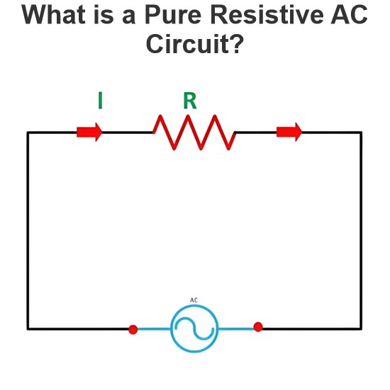
What is a Pure Resistive AC Circuit?
Pure Resistive AC CircuitA circuit containing only a pure resistanceR(in ohms) in an AC system is defined as a Pure Resistive AC Circuit, devoid of inductance and capacitance. Alternating current and voltage in such a circuit oscillate bidirectionally, generating a sine wave (sinusoidal waveform). In this configuration, power is dissipated by the resistor, with voltage and current in perfect phase—both reaching their peak values simultaneously. As a passive component, the resistor neither
Edwiin
06/02/2025
What is a Pure Capacitor Circuit?
Pure Capacitor CircuitA circuit comprising only a pure capacitor with capacitanceC(measured in farads) is termed a Pure Capacitor Circuit. Capacitors store electrical energy within an electric field, a characteristic known ascapacitance(alternatively referred to as a "condenser"). Structurally, a capacitor consists of two conductive plates separated by a dielectric medium—common dielectric materials include glass, paper, mica, and oxide layers. In an ideal AC capacitor circuit, the current
Edwiin
06/02/2025
Resistance Switching in a Circuit Breaker
Resistance SwitchingResistance switching refers to the practice of connecting a fixed resistor in parallel with the contact gap or arc of a circuit breaker. This technique is applied in circuit breakers with high post-arc resistance in the contact space, primarily to mitigate re-striking voltages and transient voltage surges.Severe voltage fluctuations in power systems arise from two main scenarios: interrupting low-magnitude inductive currents and breaking capacitive currents. Such overvoltages
Edwiin
05/23/2025
What is Biot Savart Law?
The Biot-Savart Law is employed to determine the magnetic field intensity dHnear a current-carrying conductor. In other words, it describes the relationship between the magnetic field intensity generated by a source current element. This law was formulated in 1820 by Jean-Baptiste Biot and Félix Savart. For a straight wire, the direction of the magnetic field adheres to the right-hand rule. The Biot-Savart Law is also referred to as Laplace’s law or Ampère’s law.Conside
Edwiin
05/20/2025
Inquiry
Download
IEE-Business is dedicated to serving the personnel in the global power industry.
Join IEE-Business, not only can you discover power equipment and power knowledge, but also canhnd like - minded friends!