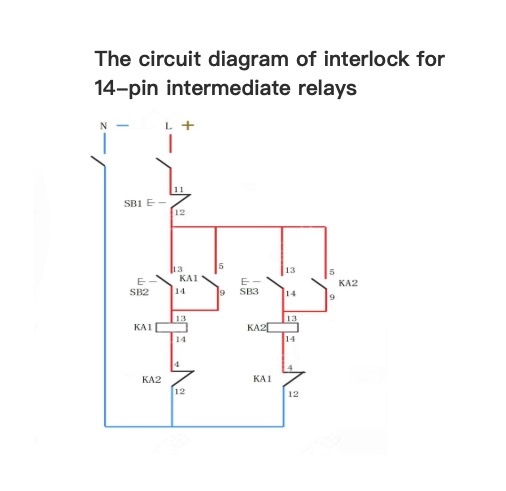
Physical diagram of interlock of 14-pin intermediate relayThe circuit diagram of interlock for 14-pin intermediate relays
07/02/2024
Consult
Tip
Consult
Tip
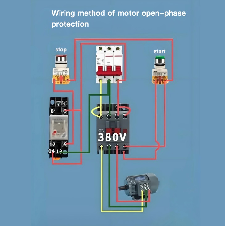
Wiring method of motor open-phase protection
07/02/2024
Consult
Tip
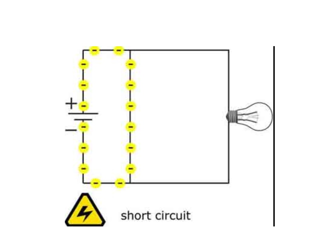
Understanding the short circuit definition and associated risks is crucial for ensuring electrical safety in homes and workplaces. By knowing the common causes of short circuits and employing preventive measures such as regular inspections, proper installation, and protective devices like circuit breakers and GFCIs, we can minimize the dangers associated with short circuits and create a safer environment for everyone.A short circuit phenomenon occurs in electrical circuits and poses potential sa
03/14/2024
Consult
Tip
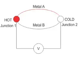
The Seebeck effect is a phenomenon that converts temperature differences into electric voltage and vice versa. It is named after Thomas Johann Seebeck, a German physicist who discovered it in 1821. The Seebeck effect is the basis of thermocouples, thermoelectric generators, and spin caloritronics. What is the Seebeck Effect?The Seebeck effect is defined as the generation of an electric potential (or voltage) across two different conductors or semiconductors that are connected in a loop and have
03/13/2024
Consult
Tip
Consider a RLC circuit in which resistor, inductor and capacitor are connected in parallel to each other. This parallel combination is supplied by voltage supply, VS. This parallel RLC circuit is exactly opposite to series RLC circuit.In series RLC circuit, the current flowing through all the three components i.e the resistor, inductor and capacitor remains the same, but in parallel circuit, the voltage across each element remains the same and the current gets divided in each component depending
03/13/2024
Consult
Tip
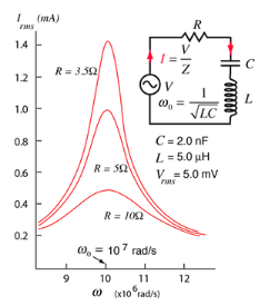
Consider a RLC circuit in which resistor, inductor and capacitor are connected in series across a voltage supply. This series RLC circuit has a distinguishing property of resonating at a specific frequency called resonant frequency.In this circuit containing inductor and capacitor, the energy is stored in two different ways. When acurrentflows in an inductor, energy gets stored inmagnetic field. When a capacitor is charged, energy gets stored in static electric field.The magnetic field in the in
03/13/2024
Consult
Tip
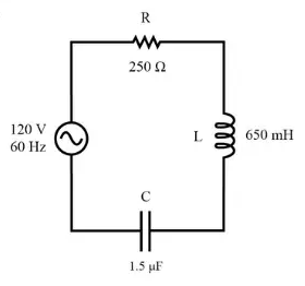
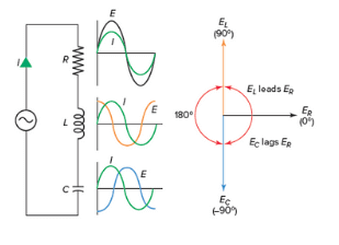
What is a Series RLC Circuit?A series RLC circuit is one the resistor, inductor and capacitor are connected in series across a voltage supply. The resulting circuit is called series RLC circuit. A circuit and phasor diagram for a series RLS circuit has been shown below.Phasor Diagram of Series RLC CircuitThe phasor diagram of series RLC circuit is drawn by combining the phasor diagram of resistor, inductor and capacitor. Before doing so, one should understand the relationship between voltage and
03/13/2024
Consult
Tip
In an RLC circuit, the most fundamental elements of a resistor, inductor, and capacitor are connected across a voltage supply. All of these elements are linear and passive in nature. Passive components are ones that consume energy rather than producing it; linear elements are those which have a linear relationship between voltage and current.There are number of ways of connecting these elements across voltage supply, but the most common method is to connect these elements either in series or in
03/13/2024
Consult
Tip
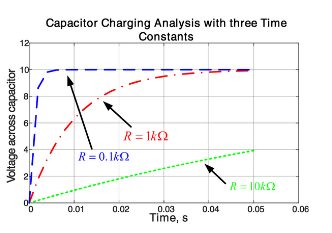
What is the Time Constant?The time constant – usually denoted by the Greek letter τ (tau) – is used in physics and engineering to characterize the response to a step input of a first-order, linear time-invariant (LTI) control system. The time constant is the main characteristic unit of a first-order LTI system.The time constant is commonly used to characterize the response of an RLC circuit.To do this, let us derive the time constant for an RC circuit, and the time constant for an RL circuit.Tim
03/13/2024
Consult
Tip


