Short Circuit Definition

The Electricity Forum
03/14/2024

Understanding the short circuit definition and associated risks is crucial for ensuring electrical safety in homes and workplaces. By knowing the common causes of short circuits and employing preventive measures such as regular inspections, proper installation, and protective devices like circuit breakers and GFCIs, we can minimize the dangers associated with short circuits and create a safer environment for everyone.

WechatIMG1482.png

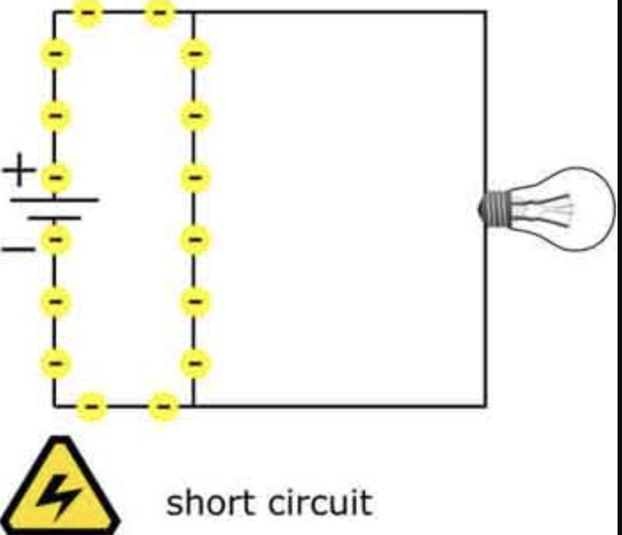
A short circuit phenomenon occurs in electrical circuits and poses potential safety hazards. To better understand the short circuit definition, one must first become familiar with the fundamentals of electrical circuits. An electrical circuit is a closed loop through which electrical current flows, and it consists of various components such as power sources, conductors, and electrical devices. A short circuit happens when an unintended, low-resistance path is formed within the circuit, causing a significant increase in current flow.


What are the different types of short circuit?

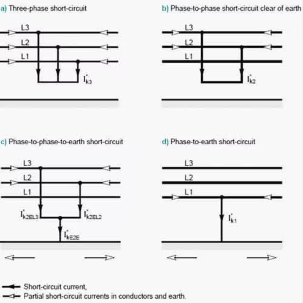
There are three main types of short circuits, each with unique characteristics and implications. These types are categorized based on the specific components of the short circuit within an electrical system. Here are the three types of short circuits:

Phase-to-Phase

This type of short circuit, also known as a line-to-line short circuit, occurs when two or more phases of an electrical system come into contact with each other. For example, this can happen when insulation between the phases is damaged or worn out, or due to a fault in the equipment or wiring. A phase-to-phase short circuit rapidly increases current flow between the affected phases, which can cause significant damage to the electrical system and generate considerable heat.


Phase-to-Neutral

A phase-to-neutral short circuit, sometimes called a line-to-neutral short circuit, occurs when a live conductor (phase) comes into contact with the neutral conductor. This can occur due to damaged insulation, loose connections, or faulty equipment. In a phase-to-neutral short circuit, the current flows between the affected phase and the neutral conductor, resulting in an increased current flow and potential damage to the electrical system.


Phase-to-Ground

This type of short circuit, also known as a ground fault, occurs when a live conductor (phase) comes into contact with a grounded object or the earth. For example, this can happen when insulation is compromised, equipment is faulty, or wiring is damaged. A phase-to-ground short circuit results in a sudden surge of current as electricity takes the path of least resistance through the ground, posing a risk of damage to electrical components, fire, and electrical shock.

WechatIMG1483.png

Each of these types can cause significant harm to electrical systems and pose potential safety hazards. Therefore, maintaining proper insulation and connections within electrical systems and implementing protective devices such as circuit breakers and ground fault circuit interrupters (GFCIs) is crucial to minimize the risks. In addition, regular inspections and maintenance of electrical equipment are also essential in ensuring the safe operation of electrical systems.

Now that we've laid the groundwork, let's delve deeper into the definition. A short circuit is defined as an abnormal connection between two nodes in an electrical circuit, allowing an excessive amount of current to flow through a low-resistance path. This can lead to various problems, including damage to electrical components, increased risk of fire, and even electrical shock.

So, how do short circuits occur? Several common causes include damaged or frayed electrical wires, improper connections, or faulty insulation. In addition, when conductive materials come into contact, they can create an unintended path for electrical current. This leads to a significant increase in current flow, resulting in a short circuit.

The dangers associated with short circuits cannot be overstated. When a short circuit occurs, it can generate intense heat, which poses a significant fire risk. Additionally, the increased current can cause conductor failure and damage to electrical components, leading to malfunctions and even total system failure. Furthermore, if an individual comes into contact with a short-circuited component, they could suffer from electrical shock, which can sometimes be fatal.

Preventing short circuits is a vital aspect of maintaining electrical safety. One of the most effective prevention methods is ensuring proper installation and maintenance of electrical systems. In addition, regular inspections should be conducted to identify and repair damaged wiring or faulty connections. Installing overload protection devices, such as circuit breakers or fuses, can also help protect against short circuits. These devices are designed to detect and interrupt the excessive current flow, thus mitigating the risk of damage or injury.

Circuit breakers play a crucial role in safeguarding electrical systems from the effects of short circuits. These devices are engineered to detect an unusually high current flow, which could indicate a short circuit or another fault. Once detected, the circuit breaker will automatically interrupt the current flow, isolating the affected section of the circuit and preventing further damage or injury.

To further understand short circuits, it's important to distinguish them from ground faults. While both phenomena involve an abnormal connection within an electrical circuit, a ground fault is a specific type of short circuit that occurs when a live conductor comes into contact with a grounded object or the earth. This can lead to a sudden current surge and pose similar risks, such as fire and electrical shock. However, ground faults can be detected and mitigated using specialized devices called ground fault circuit interrupters (GFCIs).

Remember, always be vigilant when dealing with electrical systems. If you are uncertain about a potential issue or unsure how to handle a situation, consult a licensed electrician for assistance. Electrical safety is everyone's responsibility, and understanding definition is a fundamental step in preventing accidents and promoting a safe environment.

Statement: Respect the original, good articles worth sharing, if there is infringement please contact delete.

The Electricity Forum

Electricity Forum publishes Electricity Today T&D Magazine and Intelligent Power Today Industrial Electrical Magazine. We publish electrical technical handbooks and associated digital magazine advertising supplements.

What is a Pure Resistive AC Circuit?
Pure Resistive AC CircuitA circuit containing only a pure resistanceR(in ohms) in an AC system is defined as a Pure Resistive AC Circuit, devoid of inductance and capacitance. Alternating current and voltage in such a circuit oscillate bidirectionally, generating a sine wave (sinusoidal waveform). In this configuration, power is dissipated by the resistor, with voltage and current in perfect phase—both reaching their peak values simultaneously. As a passive component, the resistor neither
Edwiin
06/02/2025
What is a Pure Capacitor Circuit?
Pure Capacitor CircuitA circuit comprising only a pure capacitor with capacitanceC(measured in farads) is termed a Pure Capacitor Circuit. Capacitors store electrical energy within an electric field, a characteristic known ascapacitance(alternatively referred to as a "condenser"). Structurally, a capacitor consists of two conductive plates separated by a dielectric medium—common dielectric materials include glass, paper, mica, and oxide layers. In an ideal AC capacitor circuit, the current
Edwiin
06/02/2025
Resistance Switching in a Circuit Breaker
Resistance SwitchingResistance switching refers to the practice of connecting a fixed resistor in parallel with the contact gap or arc of a circuit breaker. This technique is applied in circuit breakers with high post-arc resistance in the contact space, primarily to mitigate re-striking voltages and transient voltage surges.Severe voltage fluctuations in power systems arise from two main scenarios: interrupting low-magnitude inductive currents and breaking capacitive currents. Such overvoltages
Edwiin
05/23/2025
What is Biot Savart Law?
The Biot-Savart Law is employed to determine the magnetic field intensity dHnear a current-carrying conductor. In other words, it describes the relationship between the magnetic field intensity generated by a source current element. This law was formulated in 1820 by Jean-Baptiste Biot and Félix Savart. For a straight wire, the direction of the magnetic field adheres to the right-hand rule. The Biot-Savart Law is also referred to as Laplace’s law or Ampère’s law.Conside
Edwiin
05/20/2025
Inquiry
Download
IEE-Business is dedicated to serving the personnel in the global power industry.
Join IEE-Business, not only can you discover power equipment and power knowledge, but also canhnd like - minded friends!