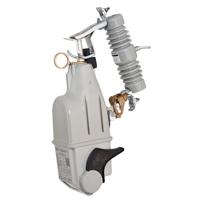
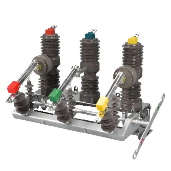
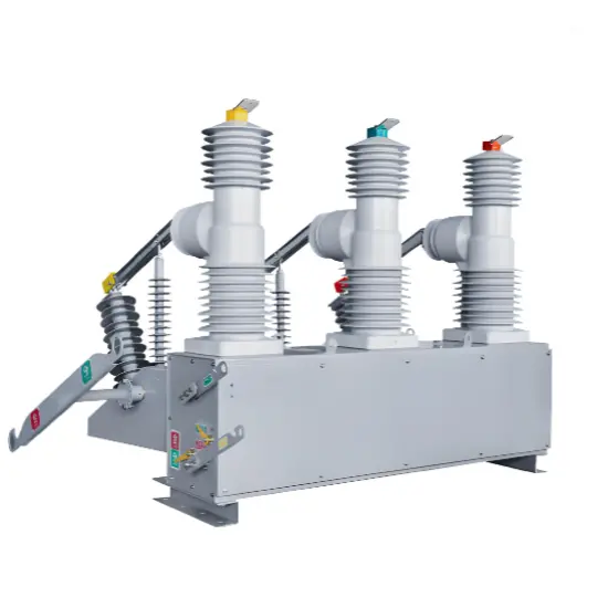
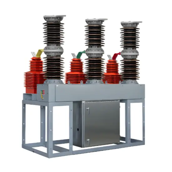
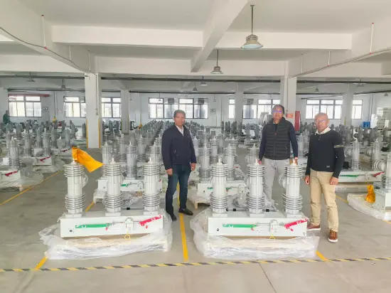
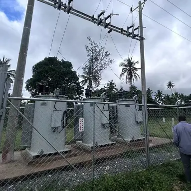
The recloser is the core execution unit in distribution automation, playing a critical role in fault detection, fault isolation, and grid self-healing. However, engineers often face multiple technical challenges in actual operation and maintenance, including protection setting, equipment coordination, and reliability assurance. This article addresses the frequent issues related to recloser protection, providing a systematic solution based on the IEC 62271-111 international standard and engineering practice.
I. Technical Principles and Fault Detection Issues
Q1: How does a recloser distinguish between transient faults and permanent faults? What consequences might result from misjudgments?
The recloser makes its judgment based on a preset reclosing sequence (such as O-0.3s-CO-15s-CO-15s-CO, according to IEC 62271-111) and current/voltage characteristics:
- Transient faults (accounting for approximately 80% of all faults, such as tree branches touching power lines or bird-related damage): After the first trip, the arc extinguishes within the deionization time, successful reclosure occurs, and the power grid automatically restores power supply.
- Permanent faults (such as open circuits or insulation breakdown): Multiple reclosings all fail. After reaching the preset maximum number of reclosings (typically 2–4 times), a lockout is triggered to prevent repeated impacts on the system.
Consequences of misjudgment: If a permanent fault is mistakenly identified as a transient fault and subjected to repeated reclosing, it will cause the arc to reignite repeatedly, leading to damage of equipment contacts, subjecting transformers to repeated short-circuit current surges, and even expanding the scope of the fault and prolonging the duration of the power outage.
Improvement direction: The next-generation controller will incorporate transient waveform analysis and adaptive algorithms, leveraging the characteristics of fault current waveforms (harmonic content and DC component) to enhance discrimination accuracy.
Q2: What are the key considerations for setting the reclosing dead time?
The setting of the reclosing delay (the time from the first trip to the first reclosure) must take into account the following factors:
- Arc deionization time: After a fault arc is extinguished, the arc channel must undergo sufficient deionization to withstand the system’s recovery voltage; typically, this takes 0.2 to 0.5 seconds.
- Dielectric strength recovery of insulating media: The dielectric strength recovery characteristics of vacuum arc chambers and line insulation.
- Coordination with upstream protection: The time delay must be coordinated with the substation feeder protection and downstream equipment to create a time-step difference, thereby preventing tripping beyond the intended level.
- System Stability and User Device Tolerance: The re-start characteristics of equipment such as motors on the load side within the reclosing interval.
Engineering Recommendation: In power grids where system operating modes change significantly, fixed-time delays may become ineffective. Adaptive reclosing—dynamically adjusting the delay based on fault type and fault phase—is emerging as a superior solution.
II. Operational and Coordination Issues
Q3: How do reclosers and sectionalizers work together to achieve fault isolation? What are the key considerations when setting time coordination intervals?
Core physical principle: The sectionalizer does not have fault-breaking capability (it cannot interrupt short-circuit currents). It must rely on the “no-voltage/no-current gap” formed when the recloser trips to isolate and disconnect the faulty section.
Cooperative logic:
- Line fault → The recloser trips according to the set sequence.
- Within the tripping interval of the recloser, the sectionalizer upstream of the fault location detects a “voltage loss—count” signal and completes disconnection and isolation.
- The recloser recloses, and only the non-fault sections regain power.
Time Zone Considerations:
- The counting action time of the sectionalizer must be shorter than the interval between successive reclosures of the recloser.
- Communication delay and the inherent operating time of switches must be taken into account.
- In urban short-feedline scenarios, it is recommended to adopt IED adaptive coordination (based on IEC 61850 GOOSE peer-to-peer communication) to achieve millisecond-level coordination.
Q4: What potential conflicts may arise when reclosers are coordinated with substation relay protection devices? How can these conflicts be avoided?
Common conflicts:
- Race Condition: When the recloser and the substation feeder protection settings are not coordinated, a fault may cause both sides to operate simultaneously, resulting in an out-of-sequence trip.
- Fixed-value mismatch: The recloser operating time does not provide sufficient grading interval with the upstream protection.
Preventive measures:
- Time-Current Curve (TCC) Coordination: Set according to strict time steps (typically with a step difference of ≥0.3s) to ensure “the nearest fault point is cleared first.”
- Unified Setting Management: Utilizing IEC 61850 intelligent coordination or centralized setting software to avoid conflicts caused by manual, decentralized configuration.
- Distributed IED real-time communication: Reclosers and feeder terminals exchange status and operation information in real time.
III. Maintenance and Reliability Issues
Q5: What are the common hardware faults of reclosers? How can we extend the service life of these devices?
Common faults:
|
Failure type
|
Typical manifestation
|
Countermeasures
|
|
Insulation degradation
|
Partial discharge exceeding the standard, flashover
|
Regular Partial Discharge (PD) Testing, Insulation Resistance Testing
|
|
Contact burnout
|
The contact resistance increases after high-current interruption.
|
Regular contact resistance measurement and monitoring of contact wear.
|
|
The mechanism is stuck.
|
Switching time drift
|
The operating mechanism should be lubricated regularly (use low-temperature grease in extremely cold environments).
|
|
Sealing failure
|
Condensation, dampness
|
IP rating verification, breather valve/heater maintenance
|
|
Vacuum level decline (vacuum arc extinguishing chamber)
|
Reduced voltage resistance
|
Withstand Voltage Test and Online Vacuum Monitoring
|
Lifespan Extension Strategy: Condition-Based Maintenance (CBM) + Environmentally Adaptive Design (salt-spray resistance, condensation prevention, wide temperature range).
Q6: How is the reliability of the recloser control power supply ensured? And how should we handle situations where the power supply is insufficient under low-load conditions?
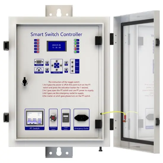
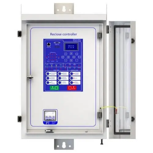
Power supply for the recloser controllerGeneral is provided in the following manner:
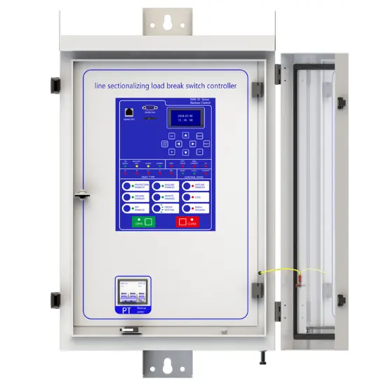
- Secondary-side power supply for PT(voltage transformers): When installed on poles, a dedicated power supply PT is configured—this is the most common power supply solution for outdoor reclosers.
- Substation station service power (AC/DC): In the on-site installation scenario, it is directly powered by the station service power supply.
- Backup Power Supply: The controller is equipped with a built-in backup battery or supercapacitor to ensure that communication and the “Last Gasp” alarm can still be maintained even when the power line loses voltage (e.g., during reclosing lockout), thereby preventing loss of fault information.
Low-load/Power-loss scenario handling: Rely on the backup power supply for automatic, seamless switchover; battery capacity design must ensure at least 24 to 48 hours of continuous monitoring (depending on project requirements).
IV. Intelligence and Future Trends
Q7: How do smart reclosers enhance the level of distribution network automation through communication technologies?
Smart Recloser (IIoT-enabled) Implementation:
- Remote monitoring: Operational status and SOE events are transmitted to SCADA/DMS in real time (IEC 60870-5-104 / DNP3.0).
- Adaptive protection: Dynamically adjusts setting values based on the power grid’s operating mode.
- Self-healing grid: In conjunction with FDIR (Fault Detection, Isolation, and Restoration) logic, the system can isolate faulted sections and restore power to non-faulted areas within 60 seconds.
- High-Impedance Ground Fault Detection (SEF): Supports 100mA-level sensitive ground fault protection, enabling the detection of high-impedance faults that conventional overcurrent protection cannot capture—this capability is a key distinction between intelligent reclosers and traditional switches, offering protection against wildfires and electric shock.
Q8: How do we evaluate the technical and economic viability of reclosers? In which scenarios is it more appropriate to deploy smart reclosers?
Evaluation Dimension: Total Cost of Ownership (TCO) = Procurement + Installation + Operation & Maintenance + Power Outage Losses. The reliability benefits achieved by smart reclosers—such as reducing the System Average Interruption Duration Index (SAIDI) by more than 70%—typically far exceed the initial investment.
Preferred deployment scenario:
- High-penetration renewable energy grid (bidirectional power flow, protection directional requirements)
- Urban Core Area (High Reliability Requirements)
- Area with frequent lightning/instantaneous faults
- Areas with difficult inspection due to mountainous terrain and forests, as well as high wildfire risk.
Conclusion
Mastering recloser protection requires a fusion of technical depth and adaptive strategies. By systematically addressing the challenges outlined above, engineers can significantly enhance grid resilience, reduce outage losses, and accelerate the transition toward a more intelligent power system.

 Login
Login