One-sentence conclusion
This solution deploys a cable distributed fault location device in ring main units/substations (supporting up to 6 cable circuits). Based on the two-terminal traveling-wave time difference method, it achieves a positioning accuracy of ±(0.5% × L + 5) meters, a fault line selection accuracy greater than 90%, and a diagnosis success rate of at least 95%. The flexible coil adopts a snap-on design for live installation, enabling integrated detection of insulation discharge warnings and precise fault location.
I. Industry Pain Points
- Underground cable faults are hidden, and the conventional process of rough testing followed by precise testing involves numerous steps and takes a long time, making it difficult to locate the fault point.
- Ring network switchgear lacks online line selection and section-location capabilities for multiple circuits, making it difficult to isolate the impact area in the event of a single-circuit fault.
- Cable insulation defects that cause discharge cannot be detected in advance, and the accumulation of these defects can eventually lead to power outages.
II. Scheme Architecture and Technical Principles
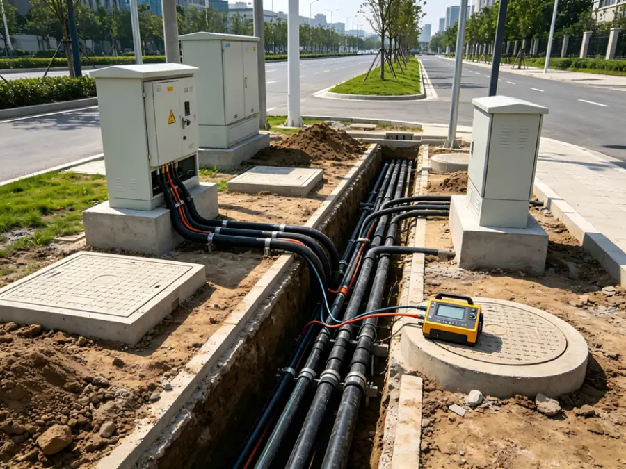
Monitoring terminal (installed inside the screen cabinet, featuring CPU, high-speed data acquisition, communication, clock, and power modules) + Power-frequency traveling-wave current sensor (flexible coil, snap-on installation on the A/B/C phase bodies at the cable termination head, enabling live installation without damaging the cable) + Cloud-based service.
- Two-terminal traveling-wave time-difference location: The fault-induced traveling wave propagates toward both ends at a constant speed. The distances from the two terminals are calculated as follows: L₁ = (L + (t₁ - t₂) · V) / 2 and L₂ = (L - (t₁ - t₂) · V) / 2. Given the length of the transmission line segment L and the wave velocity V, the fault location can be determined using the time difference measured at the two terminals.
- Wave-speed calibration: For faults occurring outside the designated zone, the wave speed is retroactively calculated using bidirectional traveling waves to eliminate wave-speed errors.
- Insulation Condition Awareness: Combining traveling-wave signal acquisition with source separation to achieve early warning of insulation defects and precise fault location in cables.
- The sensing component is integrated into a compact, card-type design made of engineering-grade plastic that is waterproof and corrosion-resistant, without causing any physical damage to the cable. The monitoring terminal is connected in bypass mode, so a single-point failure will not affect the main circuit.
III. Core Technical Indicators
| Indicator |
Parameter |
| Positioning accuracy |
±(0.5% × L + 5) m (L is the length of the monitoring interval) |
| Fault line selection accuracy |
>90% |
| Success rate of fault diagnosis |
≥95% |
| Traveling-wave/Power-frequency sampling |
Traveling wave: 1–10 MHz; Power frequency ≥6.4 kHz |
| Current range |
Traveling wave: 0.1 A to 500 A; Power frequency: 0 to 100 A; ±1 A / 100 to 400 A: ±1% |
| Clock reference |
GPS <30 ns |
| Circuit capacity |
Supports up to 6 cable lines. |
| Power supply method |
AC 220V / DC 24V / DC 12V / CT power take-off |
| Communication method |
4G/5G |
| Protection level |
IP31 (monitoring host, inside the cabinet) |
IV. Key Implementation Points
- The sensor clips onto the cable terminal heads of phases A, B, and C, supporting live installation without altering the primary circuit.
- On-site calibration of wave velocity versus line length (reverse calculation of wave velocity for faults outside the section) to ensure accurate fault location;
- In collaboration with DTU: By integrating three signals—steady-state, transient, and high-frequency traveling waves—we can compensate for the single shortcoming of DTU’s steady-state detection capability, thereby enhancing the practical applicability of distribution automation.
- Acceptance: The positioning accuracy shall be calculated based on the actual interval L, with an allowable error band; the line-selection accuracy must be determined through sample statistics (>90%).
V. Application Value
| Operations and Maintenance Phase |
Traditional model |
After deploying this solution |
| Insulation hazards |
Discharge accumulation goes unnoticed. |
Traveling Wave Insulation Condition Early Warning |
| Fault Line Selection |
Trace back and check one by one |
>90% automatic route selection |
| Fault Localization |
Rough measurement + precise measurement with multiple instruments |
±(0.5% × L + 5) m, single-locking |
| Installation method |
Power outage work |
Snap-on live installation |
FAQ
Q1: How should we interpret the positioning accuracy of ±(0.5% × L + 5) m?
The error is proportional to the monitoring interval length L (0.5% × L) plus a fixed 5 meters: For a 1-km interval, the allowable error is ±10 meters; for a 2-km interval, it is ±15 meters. The accuracy depends on the interval length, wave velocity calibration, and GPS clock accuracy (<30 ns).
Q2: Can it be installed without interrupting the power supply?
Yes, the power-frequency traveling-wave current sensor features a flexible coil snap-on design and can be installed live onto the three-phase body of the cable termination without altering the primary circuit or causing any physical damage to the cable.
Q3: What is the relationship with DTU?
Complementary rather than substitutive: While DTUs primarily rely on steady-state detection, this device supplements them with transient and high-frequency traveling-wave signals, thereby supporting the intelligent upgrade of DTUs and enhancing the practicality of distribution automation.

 Login
Login