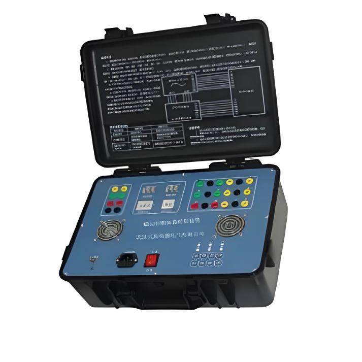
The circuit breaker simulator is an indispensable key device for power system protection commissioning and training. It enables the safe and efficient completion of complete set tests for relay protection systems without affecting actual high-voltage circuit breakers. This article focuses on the application of the Circuit Breaker Simulator 861, exploring how it addresses the core challenges in power system testing and training.
I. Challenges in Power System Testing and Training
During relay protection commissioning, periodic testing, and personnel training in power systems, directly using high-voltage circuit breakers for repeated open/close operations presents a series of problems:
- Equipment Wear: High-voltage circuit breakers have a limited mechanical lifespan; frequent operation accelerates their aging.
- High Testing Costs: Operating actual circuit breakers consumes significant energy, and outage testing affects normal system operation.
- Safety Risks: Directly operating high-voltage equipment poses safety hazards, especially for novice personnel in training.
- Lack of Flexibility: The parameters of actual circuit breakers are fixed, making it difficult to simulate various abnormal conditions and time characteristics.
II. Solutions Provided by Circuit Breaker Simulator 861
As an advanced simulation testing device, the Circuit Breaker Simulator 861 addresses the aforementioned challenges through highly realistic simulation. Its main technical features and application advantages are as follows:
1. Highly Realistic Simulation Capability
- Time Characteristic Simulation: Can accurately simulate circuit breaker trip time (20-200ms) and close time (20-500ms) with an error not exceeding ±5ms, realistically reproducing the operating characteristics of different circuit breaker models.
- Three-Phase/Phase-Segregated Operation: Supports both three-phase simultaneous operation and phase-segregated operation modes, adapting to the simulation needs of circuit breakers at different voltage levels (6kV to 750kV).
- Adjustable Impedance: Trip/close coil impedance can be selected from multiple settings such as 100Ω, 200Ω, 400Ω, etc., matching the actual coil parameters of field circuit breakers.
2. Intelligent Control and Protection
- Multiple Control Modes: Supports remote automatic control and manual operation, facilitating field commissioning.
- Self-Protection Functions: Built-in comprehensive protection mechanisms ensure the device remains undamaged under any abnormal conditions.
- Clear Status Indication: Equipped with trip/close signal indicator lights (red light indicates closed, green light indicates tripped), displaying the circuit breaker status in real-time.
3. Flexible Application Adaptability
- Wide Voltage Compatibility: Operating power supply voltage supports both DC110V and DC220V specifications, with automatic adaptation capability.
- Various Mounting Structures: Can be provided in portable or panel-mounted structures to suit different needs for field testing or fixed installation.
- Isolated Output Contacts: Output contacts are completely isolated from the operating power supply, allowing direct integration with microprocessor-based relay protection test equipment.
III. Typical Application Scenarios
1. Complete Relay Protection System Testing
For new substation commissioning or after protection device replacement, use Simulator 861 for trip/close tests to verify the correctness of the entire loop from the protection device issuing a signal to the circuit breaker executing the action, avoiding direct operation of the actual high-voltage circuit breaker.
2. Personnel Training and Skill Assessment
In training centers, this device can simulate various normal and fault conditions, allowing trainees to master circuit breaker operation procedures and fault handling skills in a risk-free environment, significantly improving training effectiveness and safety.
3. Protection Device R&D Verification
Protection device manufacturers can use Simulator 861 for product testing, simulating different circuit breaker characteristics to verify the compatibility and reliability of protection devices, thereby shortening the R&D cycle.
4. Accident Replay and Analysis
When a system fault occurs, use the simulator to recreate the accident scenario, analyze the protection operation behavior, and provide a reliable basis for accident investigation.
IV. Key Technical Implementation Points
- Parameter Setting: Correctly set trip/close times, impedance, and other parameters based on the actual parameters of the simulated circuit breaker to ensure simulation authenticity.
- Wiring Check: Carefully check the operating power supply voltage selection (DC110V or DC220V) and its compatibility with the control circuit before testing.
- Test Verification: Utilize the built-in auxiliary test circuit and a millisecond meter to accurately measure the time from protection device operation to the simulated circuit breaker action.
- Safety Measures: Even though it is a simulation device, it is still necessary to follow site safety regulations to ensure the testing process is safe and controlled.
V. Application Benefit Analysis
- Economic Benefits: Significantly reduces the number of operations of actual circuit breakers, extends equipment lifespan, and lowers maintenance costs.
- Safety Enhancement: Avoids direct contact with high-voltage equipment by personnel, reducing safety risks.
- Efficiency Optimization: The testing process is not constrained by outage schedules, accelerating project commissioning and protection setting verification progress.
- Training Effectiveness: Provides a platform for repeated practice, enhancing personnel skill levels and reducing the possibility of misoperation.