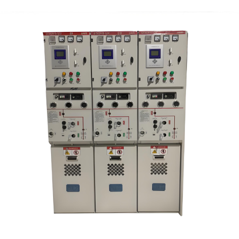
With the development of urban power grids, the number of solid-insulated ring main unit (RMU) installations has continuously increased. Their operational status significantly impacts the power supply reliability of the electrical system. The consequences of failures are severe: direct damage includes damage to the protected lines and equipment, as well as power loss; indirect consequences cause widespread customer outages, disrupting daily life, production, and even social stability.
Currently, the inadequacies of field testing methods for solid-insulated RMU equipment and the frequent occurrence of insulation faults in operational switchgear pose a serious threat to the secure operation of the power system. Partial discharge (PD) detection is an effective method for assessing the insulation condition of switchgear and is a current research focus. Performing PD detection and fault diagnosis on high-voltage switchgear provides crucial status information for condition-based maintenance and is key to ensuring safe and reliable equipment operation. In high-voltage switchgear, insulation degradation leading to insulation faults is not only caused by electric fields but can also develop due to mechanical forces, heat, or their combined action with electric fields, ultimately impacting power quality and supply reliability. To standardize and effectively implement live testing of power equipment, and referencing relevant domestic and international standards—primarily based on State Grid Corporation Production Substation Notice [2011] No. 11 "Notice on Issuing the 'Technical Specification for Live Testing of Power Equipment (Trial)'"—this research focuses on partial discharge detection for RMUs.
II. Partial Discharge Detection Methods for Ring Main Units
1. Forms of PD Energy
Partial discharge is a pulsed discharge. Besides involving charge transfer and power dissipation, the PD process also generates electromagnetic radiation, ultrasonic waves, light, heat, and new chemical byproducts. Detection methods targeting these phenomena include electrical detection, acoustic detection, optical detection, and chemical detection. Among these, electrical and acoustic methods are most commonly used, but their practical effectiveness is often limited, primarily due to significant on-site noise interference that makes it difficult to distinguish genuine PD signals. Effectively eliminating interference is crucial for improving the detection performance of PD equipment.
Detection Sensed Phenomena:
- Electrical: (TEV, UHF, HFCT sensors)
- Acoustic: (Ultrasonic sensors)
- Optical: (Visible through viewing windows in specific locations during discharge)
- Thermal: (Infrared, though detection effectiveness is limited by the RMU's fully enclosed structure)
- Chemical/Gas: (Ozone smell, etc.)
2. Detection Technologies
Numerous PD detection techniques are currently employed for switchgear, broadly categorized as Direct Methods (apparent discharge quantity detection) and Indirect Methods (TEV, ultrasonic, UHF, combined acousto-electric detection). The direct method is relative; it involves injecting a known charge quantity between the test object's terminals to create a terminal voltage change equivalent to that caused by a PD event. This injected charge is then referred to as the Apparent Discharge Quantity (Q) of the PD, measured in picocoulombs (pC). In practice, the apparent discharge quantity is not equal to the actual charge emitted at the discharge site within the test object; the latter cannot be measured directly. While the voltage waveform generated across the measuring impedance by the PD current pulse might differ from that caused by the calibration pulse, the response readings on the instruments are generally considered equivalent. Below are two mainstream RMU detection techniques.
1) Ultrasonic Detection for Solid-Insulated RMUs
By receiving ultrasonic signals transmitted through the air and measuring the acoustic pressure of the PD signal, the discharge intensity can be inferred. During ultrasonic testing, the sensor should be scanned along the seams/gaps on the switchgear surface. Reference diagrams provide guidance on typical detection locations.
2) Principle of Transient Earth Voltage (TEV) Detection
When PD occurs inside a high-voltage switchgear cabinet, an extremely short-duration pulsed current flows along the discharge channel, exciting transient electromagnetic waves. The rapidity of the discharge process results in a steep current pulse with strong high-frequency electromagnetic radiation capability. This radiation can propagate through openings in the metal enclosure, such as sealing gaskets or gaps around insulation. When these high-frequency electromagnetic waves propagate outside the cabinet, they induce a transient voltage on the outer surface relative to earth ground. This transient voltage on the earth (TEV) ranges from millivolts to volts with a rise time of a few nanoseconds. A dedicated TEV sensor placed on the outside of the cabinet can detect this signal non-invasively.
Main TEV Detection Locations (on cabinet walls opposite):
- Busbars (connections, wall bushings, support insulators)
- Circuit Breakers
- Current Transformers (CT)
- Voltage Transformers (PT)
- Cable Terminations
These components are typically located on the middle and lower sections of the front panel, the upper, middle, and lower sections of the rear panel, and the upper, middle, and lower sections of the side panels.
III. PD Localization and Phase Identification
Once sensor signals are confirmed to originate from within the equipment, Time Difference Of Arrival (TDOA) localization is used for further positional analysis. Two sensors are placed on the equipment surface; the time difference between their received signals (t2 - t1) is analyzed to determine the PD location, usually within a 1-meter range of the source.
1. Time Difference Method:
Assume the PD source is distance X from sensor 1, electromagnetic wave speed = c (speed of light), and the time difference t2 - t1 is measured via oscilloscope.
X = (t2 - t1) * c / 2
Using this formula and a tape measure, position X can be determined.
2. Plane Bisector Method:
- Move the two sensors in space until the PD signal arrival time is identical at both. This locates the discharge point on the perpendicular bisecting plane between the two sensors (Locating the Plane).
- Move the sensors within this bisecting plane until the arrival time is identical again. This locates the discharge point on the perpendicular bisecting line within that plane (Locating the Line).
- Move the sensors along this bisecting line until the arrival time is identical once more. This pinpoints the discharge location (Locating the Point).
To identify the specific phase experiencing PD, the HFCT method is used to detect signals on the ground leads (or body) of the adjacent three-phase outgoing cables. The current signal from the defective phase exhibits a larger amplitude and opposite polarity compared to the signals on the other two phases, allowing straightforward identification of the faulty phase.


