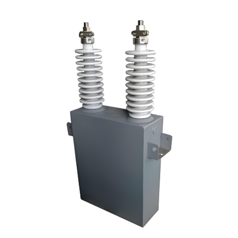
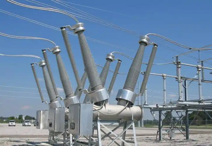
Detailed Explanation of Common Issues and Solutions for High-Voltage Capacitors

Capacitor Operating Voltage Issue
The magnitude of a capacitor's operating voltage significantly impacts its service life and output capability, making it a key monitoring indicator in the substation busbar system. The active power loss within a capacitor primarily originates from dielectric losses and conductor resistance losses, with dielectric losses accounting for over 98%. Dielectric losses have a significant influence on the operating temperature of the capacitor. This influence can be quantified by the following formula:
Pr = Qc * tgδ = ω * C * U² * tgδ * 10⁻³
Where:
- Pr represents the active power loss of the high-voltage capacitor
- Qc denotes its reactive power
- tgδ is the dielectric loss tangent
- ω is the grid angular frequency
- C is the capacitance of the capacitor
- U is the operating voltage of the capacitor
As evident from the above formula, the active power loss (Pr) of a high-voltage capacitor is directly proportional to the square of its operating voltage (U²). As the operating voltage increases, active power loss increases rapidly. This rapid increase leads to a temperature rise, consequently affecting the insulation life of the capacitor. Furthermore, prolonged operation of the capacitor under overvoltage conditions will cause overcurrent, potentially damaging the capacitor. Therefore, high-voltage capacitor systems require comprehensive overvoltage protection devices.
▲ Impact of Higher-Order Harmonics
Higher-order harmonics within the power grid can also adversely affect capacitors. When harmonic currents flow into a capacitor, they superimpose onto the fundamental current, increasing the peak value of the operating current and the fundamental voltage. If the capacitive reactance of the capacitor matches the system's inductive reactance, the higher-order harmonics will be amplified. This amplification can cause overcurrents and overvoltages, potentially leading to partial discharge within the capacitor's internal insulating dielectric. Such partial discharge can trigger failures like bulging and group fuse blowing.
▲ Busbar Loss-of-Voltage Issue
Loss of voltage on the busbar to which the capacitor is connected is another critical concern. A capacitor that suddenly loses voltage during operation can cause tripping on the substation supply side or disconnection of the main transformer. If the capacitor is not promptly disconnected under such conditions, it may experience damaging overvoltage. Additionally, failure to remove the capacitor before voltage restoration can lead to resonant overvoltage, potentially damaging the transformer or the capacitor itself. Therefore, a loss-of-voltage protection device is essential. This device must ensure the capacitor reliably disconnects after voltage loss and reliably reconnects only after voltage has been fully restored to normal.
▲ Overvoltage Induced by Circuit Breaker Operation
Circuit breaker operation can also generate overvoltage. Since vacuum circuit breakers are predominantly used for capacitor switching, contact bounce during the closing operation may trigger overvoltage. Although these overvoltages have a relatively low peak, their impact on capacitors must not be overlooked. Conversely, during circuit breaker opening (disconnection), the potentially generated overvoltages can be significantly higher and may puncture the capacitor. Therefore, it is essential to implement effective measures to mitigate the overvoltage produced during circuit breaker operations.
▲ Capacitor Operating Temperature Management
The operating temperature of capacitors is also a critical factor. Excessively high temperatures negatively impact a capacitor's service life and output capability, necessitating proactive control and management measures. Significantly, the rate of capacity decline doubles for every 10°C increase in temperature. Capacitors operating long-term under high electric fields and elevated temperatures experience gradual aging of their insulating dielectric. This aging leads to increased dielectric loss, subsequently triggering a rapid internal temperature rise. This not only shortens the capacitor's operational lifespan but, in severe cases, can even lead to failure due to thermal breakdown.
To ensure the safe operation of capacitors, relevant regulations explicitly stipulate:
- When the ambient temperature exceeds 30°C, ventilation devices should be activated to provide cooling.
- If the ambient temperature reaches or exceeds 40°C, capacitors must be deactivated immediately.
Therefore, a temperature monitoring system must be implemented to continuously track the operating temperature of capacitors in real-time. Additionally, forced-air ventilation measures are crucial to improve heat dissipation conditions, ensuring the generated heat is effectively and efficiently expelled through effective convection and radiation.