0 Gàádịnchịkwa
N'ụfọdụ ịrụ ụzọ ezi na ohere dị mkpa, ọnụọgụ ihe nkiri nke ọhụrụ ma ọ bụ ihe nkiri substation—na-akụzi okwu ụlọ ụka nke dị mkpa n'aka ọtụtụ ụlọ ụka na ọrụ mmalite ụzọ ezi ọhụrụ—ha enweghị mfe ikpeazụ ọrụ dị ka short-circuit current levels gbanwee. Bụrụ na enweghi ọrụ ịkpeazụ, ọrụ a ga-enye ịkwalite maka ihe nkiri ụzọ ezi ọhụrụ nke dị mkpa, ma ọ bụla ga-ekwu maka ọrụ ụka na pipeline nke ihe nkiri substation dị n'ụzọ, nke ga-achọ ọrụ dị elu maka ịgwọ ụka na ịmepụta.
N'ụbọchị banyere ịrụ ụzọ, mgbe ọrụ ụzọ dị elu ma short-circuit current levels dị elu, ịkpeazụ short-circuit currents ga-enwe ike ime maka ịmepụta switching devices—ihe nkiri ọzọ nke substation na-egosi ọsọ maka ịkpeazụ. Njede, mgbe ọrụ ụzọ capacity dị elu, short-circuit levels dị elu, ma short-circuit currents ga-enweghị ịkpeazụ site na ịrụ ụzọ ma ọ bụ ịmepụta capacity, ịmepụta circuit breakers dị ọzọ agaghị ekwesịghị. Ihe nkiri substation dị n'ụzọ ga-achọ ịmepụta ma ọ bụ ịmepụta main transformers, disconnectors, instrument transformers, busbars, insulators, structures, foundations, na grounding systems. Nke a ga-enye ọrụ maka ịmepụta communication lines ma ọ bụ ịgbadịha na underground communication cables.
Mgbe ọtụtụ ihe nkiri ụzọ ọhụrụ na ụlọ ụka ga-erụ n'ụzọ 220kV, short-circuit current levels ga-enweghị ịkpeazụ nke dị elu. Interrupting capacity na dynamic stability performance nke ọtụtụ 220kV circuit breakers—ma ọ bụ nke ụzọ ezi ọhụrụ—agaghị egosịrị maka short-circuit levels, nke na-ekwu maka ọrụ teknụzụ ma ọ bụ ekwupụta. Research maka ịkpeazụ short-circuit current ga-enweghị ọrụ.
1 Ọrụ Ịkpeazụ Short-Circuit Current Na Ụdị Ha
Ịkpeazụ short-circuit current ga-enweghị ịrụ maka ụzọ structure, operation, ma ọ bụ ihe nkiri. Ọrụ zuru oke gụnyere:
- a. Adjustment ụzọ Structure
Gụnyere ịrụ ụzọ voltage nke dị elu, splitting ụzọ voltage nke elu/busbars, ma ọ bụ grid separation.
- Ịrụ ụzọ voltage nke dị elu: Ga-achọ ịkwalite dị elu na-egosi ọsọ maka ụdị environment.
- Splitting ụzọ voltage nke elu/separation: Ịmepụta dị ọhụrụ nwere ọrụ ịkpeazụ dị elu, mana ọ ga-echeta ọrụ ụzọ safety margins na operational flexibility, nke na-egosi ọsọ maka ọrụ dị ọhụrụ.
- b. DC Interconnection Technology
DC interconnection ga-enweghị ịkpeazụ short-circuit currents, mana ịkwalite maka converter stations n'aka ụbọchị ga-enweghị ịkwalite dị elu. Maka interconnections nke elu na power exchange nke elu, ọrụ a ga-enweghị ịkwalite dị elu.
- c. High-Impedance Transformers
Ihe nkiri high-impedance transformers nwere ọrụ ịkpeazụ short-circuit currents n'aka low-voltage side. Mana, ha na-enweghị losses n'aka steady-state operation, nke na-ekwu maka ọrụ ụzọ economy.
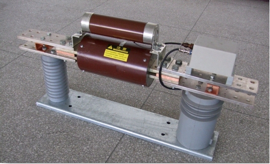
- d. Series Reactors
Series reactors, nwere manufacturing technology nke dị ọrụ na ọrụ ịkpeazụ nke dị elu, dị n'aka ụzọ ụka auxiliary systems ma ọ bụ 10–35kV substations. Mana, ịmepụta ha n'aka ultra-high-voltage systems ga-enweghị network losses na ọ ga-echeta ọrụ ụzọ stability, nke na-ekwu maka ọrụ ha.
- e. Equipment Capacity Expansion and Retrofitting
Ịmepụta circuit breakers ma ọ bụ retrofitting ihe nkiri substation n'aka ọrụ maka short-circuit currents nke dị elu na-egosi ọrụ, mana ọ ga-achọ ịkwalite dị elu na ịmepụta nke dị ọhụrụ, nke na-ekwu maka ọrụ ekwupụta na timeliness.
Mgbe ọrụ zuru oke na-egosi ọsọ, ịrụ ọrụ ịkpeazụ ọhụrụ nwere ọrụ maka ụzọ ezi ọhụrụ ga-enweghị ọrụ. Fault Current Limiter (FCL) ga-enweghị ọrụ maka ọrụ a, na-egosi ọ bụ ụzọ ọhụrụ nke Flexible AC Transmission Systems (FACTS).
2 Ịmepụta Fault Current Limiters (FCL) N'ụzọ Ezi
2.1 Model na Basic Principles nke FCL
Basic principle nke FCL na-egosi series reactor current-limiting technology, improved maka power electronics maka ịkpeazụ ụdị traditional series reactors (e.g., high steady-state losses na impacts maka ọrụ ụzọ stability). Ụzọ model ya ga-enweghị ịrụ: "No reactance under normal operation; rapid insertion of reactance during faults to limit current."
- Normal operation: Switching device closed, FCL equivalent impedance near zero, no impact on the system.
- Fault condition: Switch rapidly opens, inserting the current-limiting reactor to suppress short-circuit current.
Core components nke FCL gụnyere four key elements:
- Fast fault current detection element: Monitors system current in real time and quickly identifies short-circuit faults.
- Fast switching device: Acts rapidly during faults to switch between "no reactance" and "reactance" states.
- Current-limiting reactor: Core current-limiting component, suppressing short-circuit current through impedance.
- Overvoltage protection element: Prevents overvoltage during fault switching, protecting system equipment.
2.2 Functions and Design Requirements of FCL
2.2.1 Core Functions of FCL
FCL provides a new approach to fault current limitation in power systems and is a critical component of modern power systems. Its advantages include:
- Reducing circuit breaker burden: Higher voltage levels correspond to larger, harder-to-interrupt fault currents. FCL directly reduces the interrupting current of circuit breakers, extending equipment lifespan.
- Improving system stability: Rapidly limiting short-circuit currents reduces line voltage drops and generator out-of-step probabilities, enhancing power angle, voltage, and frequency stability.
- Increasing equipment and line utilization: If FCL acts before the short-circuit current peaks, it reduces requirements for thermal and dynamic stability limits, thereby increasing the actual transmission capacity of lines.
- Optimizing voltage quality: Rapid current limitation before fault clearance shortens voltage sag duration on non-faulted lines, ensuring grid voltage stability.
- Reducing interference with surrounding facilities: Limiting short-circuit currents in high-voltage grids reduces electromagnetic interference with nearby communication lines and railway signaling systems.
2.2.2 Design Requirements for FCL
To adapt to power system operating characteristics, FCL must meet the following design standards:
- No impact on the system during normal operation (voltage drop near zero).
- Fast response during faults (within 1–2 ms), limiting both peak and steady-state short-circuit currents without side effects such as overvoltage.
- Automatic reset after fault clearance without manual intervention.
- No interference with the normal operation logic of protective relays.
- Reasonable cost and high cost-effectiveness, meeting utility engineering application needs.
2.3 Comparison of Various FCL Implementation Schemes
2.3.1 Scheme Comparison
|
Scheme Type
|
Core Advantages
|
Main Limitations
|
Maturity
|
|
Mechanical Switch FCL
|
-
|
Slow response, high cost, impractical
|
Obsolete
|
|
New Material FCL
|
Simple structure, high reliability, effective limiting
|
Dependent on new materials, delayed practicality
|
Experimental
|
|
Power Electronics FCL
|
Flexible control, fast response, suited for medium-low voltage systems
|
High initial cost
|
Engineering feasible
|
- Conclusion: New material-based (especially superconducting) and power electronics-based FCLs are currently the optimal solutions. The former is simple and reliable but limited by material technology; the latter offers strong controllability, and with declining power electronics costs, it has become engineering feasible, making it the most promising R&D direction.
2.5 Future Research Directions for FCL
Future research on FCL should focus on "performance optimization, functional integration, and engineering adaptation." Key directions include:
- Continuously adjustable impedance converters: Moving beyond the current "two-state impedance (zero or infinite)" limitation to develop responsive, continuously adjustable impedance converters that dynamically match higher impedance with larger fault currents. These should also incorporate power factor compensation and overvoltage absorption, combined with control theories (e.g., negative feedback, PID control) to enhance system automation.
- Integration with FACTS controllers: Developing comprehensive control devices that combine FCL with other FACTS components (e.g., SVG, SVC) to improve overall cost-effectiveness and advance controllable AC transmission and distribution systems.
- Key technology breakthroughs:
- Impact mechanisms of FCL on power system stability.
- Coordination logic between FCL and protective relays.
- Optimization of ultra-fast fault signal detection systems and controllers.
- Effects of FCL on power quality (e.g., harmonics, voltage fluctuations) and mitigation measures.
3 Conclusion
- a. Short-circuit current limitation in power systems has become a critical issue requiring urgent resolution. As a new protection device, the Fault Current Limiter (FCL) offers an effective solution, and developing FCLs adapted to modern grids holds significant theoretical and engineering value.
- b. Power electronics-based FCLs already possess a theoretical foundation and engineering practicality. Their excellent control performance and declining costs of power electronic devices indicate broad development prospects.
- c. With the advancing development of FACTS/CusPow technologies, FCL—as a key member of the FACTS family—should not only independently address current limitation issues in transmission and distribution grids but also collaborate with other FACTS controllers to further promote the development of controllable AC transmission and distribution systems.