1 Buod ng Pagsusumamo
Mga Hamon sa Pagmamanage ng Voltage sa Modernong Mga Distribution Network:
- Mga long-distance feeders na nagdudulot ng pagbaba ng voltage;
- Integrasyon ng mga distributed energy resource (DER) na nagdudulot ng bidirectional power flow;
- Pagbabago ng load na nagdudulot ng madalas na pagbabago ng voltage.
Teknikal na Katangian ng Step Voltage Regulators (SVRs):
- Naglalapat ng tap-changing technology upang baguhin ang ratio ng winding turns ng transformer, na nagpapahintulot ng ±10% na range ng pag-aadjust ng voltage (karaniwang 32 steps, 0.625% bawat step);
- Ang pangunahing mga benepisyo ay nasa real-time dynamic adjustment capabilities kasama ang maraming control strategies, na nagbibigay ng flexible voltage support para sa distribution grid.
Trends sa Teknolohiya ng Pag-unlad:
- Nag-evolve mula sa basic mechanical tap switches hanggang sa integrated systems na may power electronics, adaptive control algorithms, at intelligent communication modules;
- Halimbawa: Ang ABB SPAU341C ay may Line Drop Compensation (LDC) functionality, na sinusimula ang mga katangian ng line impedance para sa precise voltage control sa remote load points;
- Ang paggamit ng magnetically held relays at TRIACs ay nagpapababa ng mga pagkawala ng equipment at footprint, na nagpapahusay ng deployment flexibility at cost-effectiveness.
2 Teknikal na Prinsipyong & Struktura
Pangunahing Mechanism ng Voltage Regulation:
- Nagpapahintulot ng voltage regulation sa pamamagitan ng pagbabago ng ratio ng winding turns ng transformer, depende sa tap-changing technology ng On-Load Tap Changers (OLTCs).
Closed-Loop Feedback Control Process:
- Ang mga voltage transformers ay patuloy na kumukuha ng mga signal ng system voltage;
- Ang mga error signals ay ginagawa sa pamamagitan ng paghahambing ng mga acquired values sa set reference values;
- Ang control unit ay nagpapasya kung paano ang direksyon ng tap change (boost/buck) at ang laki ng step batay sa error signal.
Pangunahing Teknikal na Parameters ng Modernong SVRs:
- Bilang halimbawa, ang SPAU341C: Suportado ang fine voltage adjustment steps ng 0.625%, na nagpapahintulot ng 32-step precise voltage regulation sa loob ng ±10% range.
2.1 Pangunahing Komponents
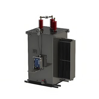
- On-Load Tap Changer (OLTC): Ang core actuator ng regulator, na gumagamit ng vacuum interrupters upang mabawasan ang arcing. Ang transition resistors ay nag-uugnay sa current continuity sa panahon ng switching, na nagpapahintulot ng hindi ma-disrupt ang supply ng load. Ang modern designs ay gumagamit ng dual-resistor transition technology, na nagpapababa ng switching times sa 40-60 milliseconds.
- Control Module: Itinayo sa high-performance microprocessors (ARM/DSP), na naglalaman ng maraming control strategies. Ang ABB SPAU341C ay gumagamit ng modular architecture, na binubuo ng connection modules, I/O modules, at automatic voltage regulation module, na sumusuporta sa continuous self-monitoring para sa real-time hardware at software diagnostics.
- Measurement and Protection Unit: Ang mga Voltage/Current Transformers (hal. PT1, PT2, TA1) ay patuloy na kumukuha ng mga parameter ng system. Ang mga units ay may three-phase overcurrent at undervoltage blocking functions. Kapag nakadetect ng short circuit o severe voltage dip, ang tap-changing operations ay agad na ibinibigay upang maprotektahan ang equipment.
- Communication and Operation Interface: Sumusuporta sa Ethernet, GPRS, at iba pang communication protocols para sa remote monitoring at parameter settings. Ang display module ay nagbibigay ng local operating interface, na nagpapakita ng mga key parameters tulad ng setpoints at measured values sa real-time.
2.2 Pangunahing Operational Characteristics
|
Karakteristika
|
Teknikal na Deskrripsyon
|
Application Value
|
|
Line Drop Compensation (LDC)
|
Gumagamit ng virtual impedance parameters (R/X) settings upang makompensuhan ang line voltage drop.
|
Nagpapahintulot ng precise voltage control sa remote load points; nagwawala ng karunungan para sa additional measurement devices.
|
|
Bidirectional Power Flow Support
|
Naglalapat ng hybrid switches na may back-to-back thyristors at magnetic latching relays.
|
Nag-aadapt sa mga scenario na may DER integration; sumusuporta sa voltage regulation sa ilalim ng reverse power flow.
|
|
Parallel Operation Capability
|
Sumusuporta sa parallel operation ng hanggang sa 3 transformers sa pamamagitan ng Master/Slave o Circulating Current Minimization principles.
|
Nagpapalawak ng system capacity; sumasagot sa mga demand ng high-load density areas.
|
|
Fault Ride-Through (FRT) Capability
|
Mayroong voltage sag detection at fast restoration logic.
|
Nagpapataas ng continuous supply para sa sensitive loads; nagpapahusay ng reliability ng power supply.
|
3 Application Solutions sa Distribution System Design
3.1 Typical Application Scenarios
- Long Radial Feeders: Isang classic SVR application. Sa rural distribution networks, ang 10kV lines kadalasang tumataas hanggang 15km, na nagdudulot ng severe voltage deviation sa dulo ng feeder. Ang pag-deploy ng SVRs mid-line o sa dulo ng feeder ay epektibong nagkompensate sa mga voltage drops. Ang engineering practices ay nagpapakita na ang isang SVR ay maaaring palawakin ang radius ng feeder ng 30%, na nagpapahusay ng voltage compliance rate sa dulo ng feeder mula sa mas mababa sa 70% hanggang sa higit sa 98%, na nagpapababa ng malaking upgrade costs ng line.
- High-Density Urban Distribution Networks: Nagtatagpo ng mga hamon ng load fluctuation at voltage mismatch. Ang mga SVRs ay karaniwang inilalapat sa substation outlets o ring main unit (RMU) nodes. Sa isang city commercial district retrofit project, ang pag-install ng SVRs sa 4 key nodes ay nagresulta sa pagbaba ng peak-hour voltage fluctuation mula ±8% hanggang ±2%, habang nagpapababa rin ng line losses ng 12% sa pamamagitan ng reactive power optimization.
- High DER Penetration Areas: Nangangailangan ng pag-manage ng bidirectional power flow challenges. Kapag ang PV penetration ay lumampas sa 30%, ang traditional distribution networks kadalasang nag-eexperience ng mga voltage violations. Ang mga SVRs ay awtomatikong nag-aadjust ng control logic sa pamamagitan ng reverse power mode, na aktibong nagpapababa ng voltage sa panahon ng generation surplus. Ang isang PV demonstration project na gumagamit ng coordinated control between SVRs at PV inverters ay nagpataas ng local PV hosting capacity ng 25% at nagpababa ng curtailment rates ng 18%.
3.2 Control Strategy Optimization
- Voltage-Var Optimization (VVO): Coordinates SVRs with shunt capacitor banks to minimize system losses.
- Multi-Stage Coordinated Control: Para sa cascade installations ng multiple SVRs sa complex networks, kailangang iwasan ang mga control conflicts. Ang Time Delay Coordination Method ay ang pinakapraktikal na solusyon—setting the upstream SVR's delay (karaniwang 30-60 seconds) to at least double the downstream SVR's delay. Upon detecting a voltage violation, the downstream SVR acts first. If the issue persists beyond its delay window, the upstream SVR then intervenes. This approach significantly reduces unnecessary tap operations (by up to 40%) while maintaining voltage stability.
- Adaptive Control Strategies: Ang modernong SVRs (hal. SPAU341C) ay may self-learning algorithms upang iprognostiko ang mga pangangailangan ng voltage adjustment batay sa historical load profiles. Ang sistema ay awtomatikong pre-adjusts tap positions sa panahon ng mga similar daily load patterns (hal. morning peaks), na nagpapababa ng voltage adjustment response times mula sa minutes hanggang sa seconds. Ang strategy na ito ay partikular na suitable para sa PV output fluctuations o scenarios na may concentrated electric vehicle (EV) charging.
3.3 Scenario Selection Matrix
|
Application Scenario
|
Equipment Selection Criteria
|
Control Strategy
|
Expected Outcome
|
|
Long Radial Feeders
|
Large adjustment range (±15%), strong heat dissipation
|
LDC + Delayed Coordination
|
End voltage boost: 8-12%, Feeder radius extension: 30%
|
|
High-Density Urban Areas
|
Fast response (<1s), compact design
|
VVO Coordination + Load Forecasting
|
Voltage fluctuation <±2%, Network losses reduction: 10-15%
|
|
High DER Penetration Areas
|
Bidirectional flow support, high overload capability
|
Reverse Power Mode + Source-Grid Coordination
|
PV hosting capacity ↑25%, Voltage compliance rate >99%
|
4 Performance Optimization & Innovative Technologies
Loss Reduction Technology:
Hybrid switching technology is a core innovation for minimizing SVR losses. Traditional mechanical tap changers suffer from contact resistance in the tens of mΩ and significant arcing losses. The modern solution employs a hybrid structure of Magnetic Latching Relays and Back-to-Back Thyristors:
- Steady-State Conduction: Handled by the Magnetic Latching Relay (contact resistance <1mΩ)
- Transition Moment: The Back-to-Back Thyristor provides a current path (trigger time <2μs)
- Post-Switch Steady-State: Mechanical contacts close again, semiconductor devices turn off.
This design reduces switching losses by 80%, shrinks equipment volume by 40%, achieves arc-less switching, and extends equipment lifespan. Actual operating data shows hybrid-switch SVRs incur 55% lower annual maintenance costs compared to traditional models.
Topology Innovation also contributes significantly. The Cascaded Voltage Regulator adopts a hybrid structure with a series transformer and shunt capacitor, offering three optional operating modes:
- Equivalent Series Compensation Mode: Targets voltage boost at the end of long lines.
- Voltage-Var Adjustment Mode: Coordinates voltage and reactive power optimization.
- Pure Voltage Regulation Mode: Enables rapid response to voltage sags.
This design reduces system losses by 15-20% at the same capacity while improving fault ride-through capability.
5 Application Cases & Practical Experience
5.1 Voltage Boost on Rural Long-Distance Feeder
- Project Background: A 28km 10kV feeder in a mountainous area supplied dispersed loads. End voltage during peak hours dropped to 8.7kV (below standard lower limit: 9.7kV), failing to meet power requirements for irrigation pumps. Traditional solutions required a new substation at over ¥8 million cost.
- Solution: Two ABB SPAU341C regulators deployed in series at the 12km and 22km points, utilizing a Master-Slave coordination strategy.
- Device Configuration: Each SVR: 800kVA, ±15% range, LDC-enabled.
- Control Strategy: Master station (22km) delay: 60 seconds; Slave station (12km) delay: 30 seconds.
- Compensation Parameters: Virtual R = 0.32Ω, X = 0.45Ω (simulating line impedance).
- Results:
- End voltage stabilized at 9.8-10.2kV; compliance rate rose from 61% to 99.6%.
- Insufficient starting torque issue for pumps during irrigation season peak load completely eliminated.
- Total investment: ¥1.8 million (77.5% cost reduction vs. new substation).
- Annual energy loss reduction: ~150 MWh, corresponding to energy cost savings of ~¥120,000.
5.2 Power Quality Improvement in Urban High-Density Area
- Project Background: Within an urban RMU's supply area, clustered commercial complexes and EV charging stations caused voltage fluctuations reaching ±8%. Transformer loading reached 130% during peak hours.
- Solution: Deployment of an SVR + Dynamic Var Compensation (SVG) system at the RMU inlet.
- Device Selection: SPAU341C Regulator (1250kVA) with ±200kVar SVG.
- Control Architecture: VVO coordination controller performing joint optimization every 5 minutes.
- Prediction Algorithm: Deep learning-based load forecasting (accuracy >92%).
- Results:
- Voltage fluctuation controlled within ±2% (compliant with IEEE 519).
- Transformer loading reduced to 85%, freeing up 30% capacity.
- Comprehensive line losses reduced from 7.8% to 6.2%, yielding annual savings ~¥80,000.
- Charging pile failure rate reduced by 40%; user complaints decreased by 90%.


