• WDYZ-205 Zinc oxide arrester live tester
  • WDYZ-205 Zinc oxide arrester live tester
WDYZ-205 Zinc oxide arrester live tester
$2000.00
Model
MOAT-205
Basic info
Brand Wone
Model NO. WDYZ-205 Zinc oxide arrester live tester
Rated frequency 50Hz
Series WDYZ-205
Product Detail

Description

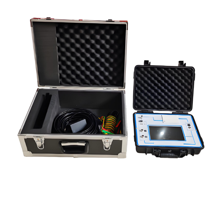
WDYZ-205 Zinc Oxide Arrester Live Tester completely solves the problem of on-site live test of 6-35kV Zinc Oxide Arrester. Realize the on-line uninterrupted test of zinc oxide arrester!

 No need to climb poles, no wiring, fast and accurate test!

The tester is suitable for voltage levels of 6kV-500kV and has a variety of sampling methods. It is a special instrument for testing the electrical performance of zinc oxide arresters.

 Dangerous defects such as damping of the internal insulation of the equipment and aging of the valve plate.

Specifications

  •  Working power supply:

    Host - internal battery power supply, charging time > 3 hours, continuous work > 8 hours.

    Wireless Current Clamp - Powered by internal battery, charging time > 1 hour, continuous working > 8 hours.

  •  Measuring range:

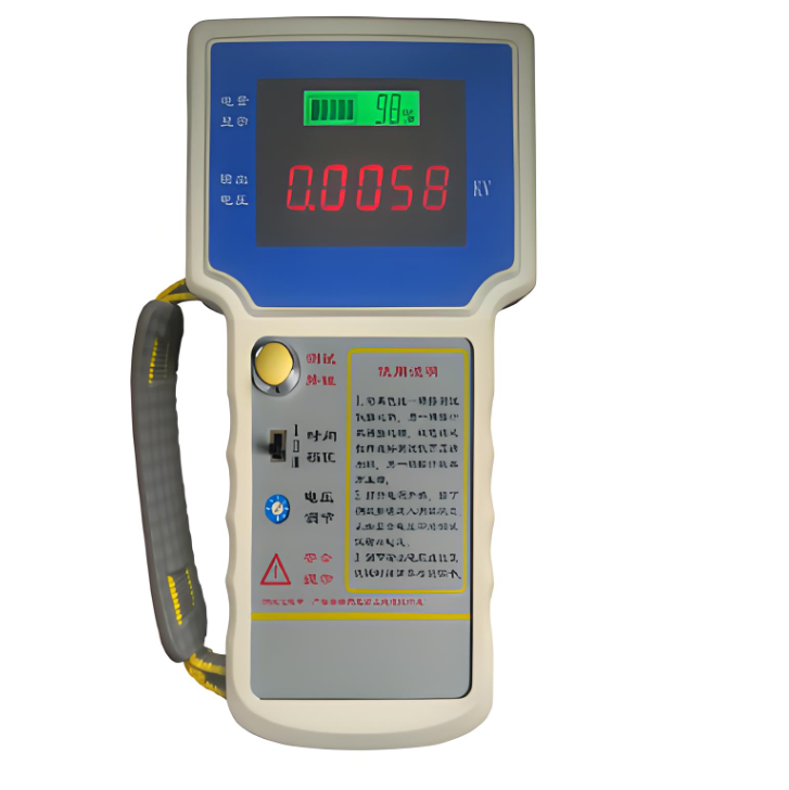
    Host leakage current: 0.000-20mA (expandable).

    Host voltage: 30-250V (expandable).

    Wireless current clamp current: 0-20mA (expandable).

    Wireless current clamp voltage: 0-60kV (bare wire 0-35kV).

    Wireless current clamp jaw: Ø33mm.

    Wireless current clamp transmission distance > 30 meters.

  •  Measurement accuracy:

    Current: When the full current is >100μA: ±5% reading ±1 word.

    Voltage: When the reference voltage signal is >30V: ±5% reading ±1 word.

  •  Measurement parameters:

      Leakage current: full current waveform, fundamental RMS value, peak value.

      Leakage Current Resistive Component: Waveform.

      1, 3, 5, 7, 9 valid values.

      Positive peak Ir+ Negative peak Ir-.

     Capacitive current fundamental.

     Voltage: voltage waveform, voltage RMS.

      Phase angle difference, power consumption.

  •  Lithium battery parameters:

    Charging time > 2.5 hours.

    Continuous working time > 7 hours.

    Intermittent working time > 7×24 hours.

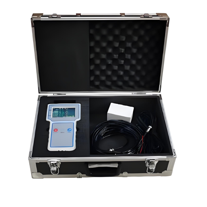
  •      Main box size and weight:

     Main box: 42cm×34cm×18cm.

      Host: 7.0kg.

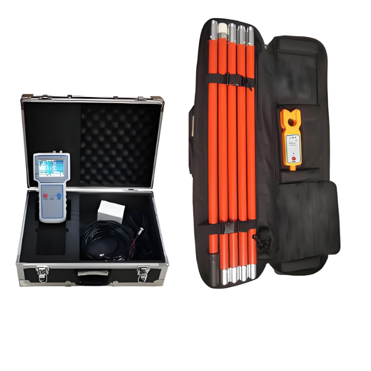
  • Insulation rod size and weight:

    Wireless current clamp 70mm×30mm×250mm 0.5KG.

    Insulation rod Ø30mm×1000mm 5 pieces 5.0KG.

    Wire pack box 1000×100mm×240mm 6.2KG.


Know your supplier
Wone
Main Categories
High Voltage Electrical Apparatus/Low Voltage Electrical Apparatus/Wire cable/Instrument meters/New energy/Tester/Production equipment/Generator/Electrical fittings/Integrated Electrical Equipment
Business Type
Design/Manufacture/Sales
Highest Annual Export (USD)
$50,000,000
Professional Experience
1 years
Workplace
65666m²m²
占位
占位
Related Products
Related Knowledges
Ensuring Reliability: A Deep Dive into Transformer Maintenance
IntroductionElectric transformers are the backbone of modern power distribution systems, silently enabling the reliable delivery of electricity to homes, businesses, and industries. As these critical assets age and the demand for uninterrupted power grows, the importance of diligent transformer maintenance has never been greater. This essay explores the essential role of transformer maintenance, highlighting the value of proactive care, the impact of advanced diagnostic technologies, and the tra
Vziman
09/03/2025
How does a transformer work?
Transformer Operation PrincipleA transformer is an electrical device that operates on the principle of electromagnetic induction to transfer electrical energy from one circuit to another. It enables the adjustment of voltage levels within an alternating current (AC) system, either stepping up (increasing) or stepping down (decreasing) voltage while maintaining the same frequency.Working Principle:Basic ComponentsA transformer consists of two coils, known as windings—the "primary winding" connect
Rockwell
09/03/2025
Constant testing of high-voltage cable lines
1. Definition of High-Voltage Cable Line Constant TestingHigh-voltage cable line constant testing refers to the systematic measurement, using specialized instruments, of electrical parameters such as resistance, inductance, capacitance, and conductance before a cable line is commissioned or after major maintenance. The aim is to obtain fundamental data characterizing the electromagnetic properties of the cable, serving as a critical testing phase that provides accurate parameter support for powe
Oliver Watts
09/03/2025
Technical Analysis of 220 kV High-Voltage Cable Construction in Winter
1.Work Environment Requirements and Safeguard MeasuresBased on technical requirements for cable equipment storage, laying, transportation, laying, transposition, testing, and cable terminations, the project owner and construction units have conducted extensive trials and implemented protective measures regarding ambient temperature, humidity, bending radius, traction control, and route optimization. These measures ensure high-voltage cable quality and on-site safety under harsh winter conditions
James
09/03/2025
Withstand voltage test of high-voltage cables
Withstand voltage test is an insulation test, but it is a destructive test that can reveal insulation defects difficult to detect in non-destructive testing.The test cycle for high-voltage cables is three years, and it must be conducted after non-destructive tests. In other words, the withstand voltage test is performed only after all non-destructive tests have been passed.Most high-voltage cables used today are cross-linked polyethylene (XLPE) cables, which can have large cross-sections and cov
Oliver Watts
09/03/2025
Analysis of Abnormal Causes of High-Voltage Cable Grounding Circulation and Typical Cases
I. Introduction to Cable Grounding Loop CurrentCables rated 110 kV and above use a single-core structure. The alternating magnetic field generated by the operating current induces a voltage on the metallic sheath. If the sheath forms a closed circuit through the earth, a grounding loop current will flow on the metallic sheath. Excessive grounding loop current (loop current exceeding 50 A, more than 20% of the load current, or a ratio of maximum-to-minimum phase current greater than 3) not only a
Felix Spark
09/03/2025
×
Inquiry
Download
IEE-Business is dedicated to serving the personnel in the global power industry.
Join IEE-Business, not only can you discover power equipment and power knowledge, but also canhnd like - minded friends!