

| Brand | Wone |
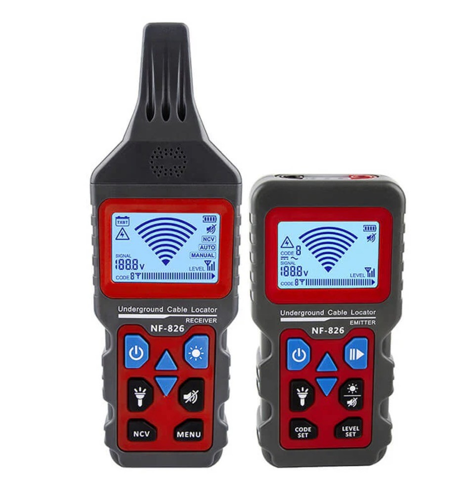
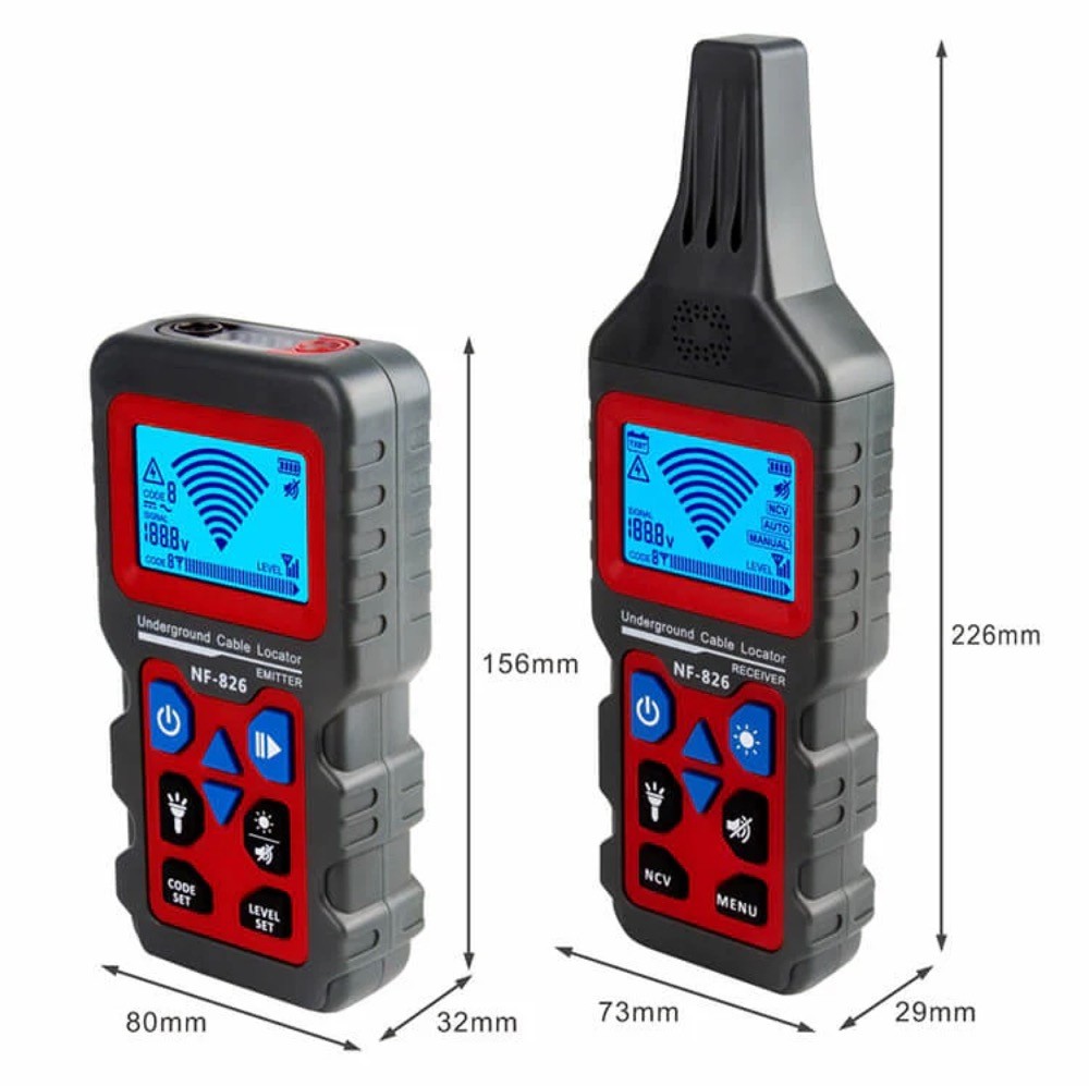
| Model NO. | NF-826 Wire Tracer for Underground and Wall Electrical Wires and Pipes |
| Max Depth Range | 1000m |
| Max Cable Length | 2m (80 inch) |
| Series | NF |
Features
Circuit Tracer: Trace circuits and find electrical wires and metal (copper, network, power) cables in drywall or underground. The Max detection range is 2m (80in).
Wiring Fault Locator: Tone locating faults like breaks, open circuits, and short circuits in wires and cables. Flexible scanning strength for various environments.
Breaker Finder: Attach the transmitter device to a socket via adapters. Locate socket breakers on the box with one tap.
Voltmeter: The transmitter has an integrated AC / DC voltmeter for linear measurement of 12-400V DC/AC voltage.
Electricity Detector: The receiver (the tone probe) can detect AC voltage over 60V without touching the object.
Pipe Locator: Detect the wiring and direction of underground water, heating, and gas pipelines without breaking the lawn and floor. Locate the breakpoints in the pipe easily.
A Built-in LED Light: An internal LED light illuminates the dark environment for easy operation.
Certification: Passes RoHS, FCC, and CE compliance testing.
Fair Price: Compared to expensive Klein and Fluke wire tracers, NF-826 is a lot more friendly to your budget.
Versatile Accessories for Precision: Provide a comprehensive set of accessories tailored for diverse scenarios, ensuring your wire tracing needs are met with precision and efficiency. Elevate your experience with our all-in-one solution for seamless connectivity troubleshooting.
Techical parameters

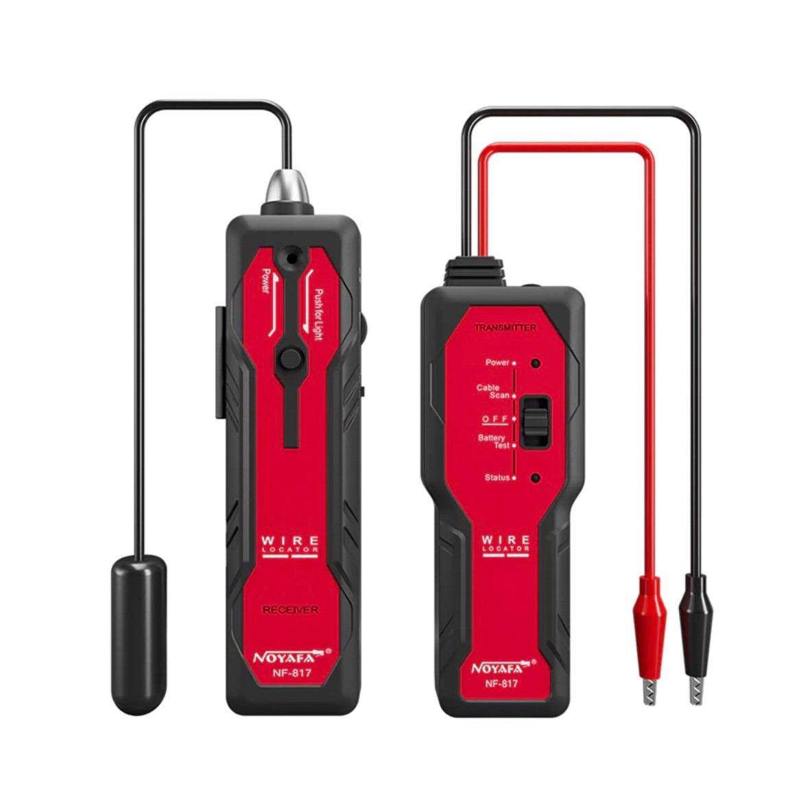
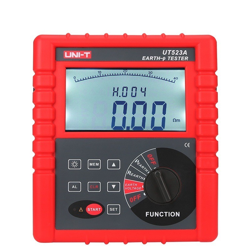
Accessories


-
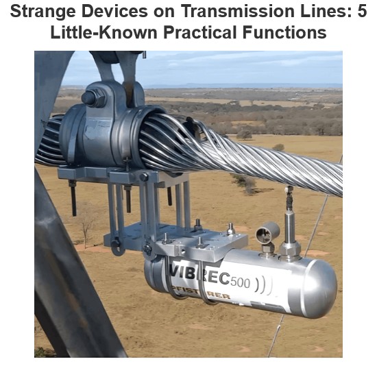 Strange Devices on Transmission Lines: 5 Little-Known Practical Functions(1)1 Aviation Warning SpheresAviation warning spheres, also known as reflective safety spheres, are used on overhead transmission lines near airports, especially on extra-high-voltage (above 220kV) lines and river-crossing transmission lines. Highly visible aviation marker spheres (aviation warning spheres) must be installed along the lines to provide warning signals.The aviation marker sphere (aviation warning sphere) has a diameter of ф=600mm. The sphere can be manufactured in various bright coloLeon09/04/2025
 -
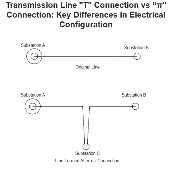 Transmission LineIn transmission lines, a "π" connection involves breaking the original line from Substation A to Substation B and inserting Substation C, forming a "π" configuration. After the "π" connection, the original single line is divided into two independent transmission lines. Following the "π" connection, Substations B and C may both be powered by Substation A (in this case, Substation C receives power via a feeder from Substation B's busbar, or possibly from another voltage point within Substation B);Encyclopedia09/04/2025
 -
 What are the principles of forced re-energization of transmission lines?Principles of Forced Re-energization of Transmission LinesRegulations for Forced Re-energization of Transmission Lines Correctly select the forced re-energization end of the line. If necessary, change the connection configuration before forced re-energization, taking into account the reduction of short-circuit capacity and its impact on grid stability. There must be a transformer with its neutral point directly grounded on the busbar at the forced re-energization end. Pay attention to the impactEdwiin09/04/2025
 -
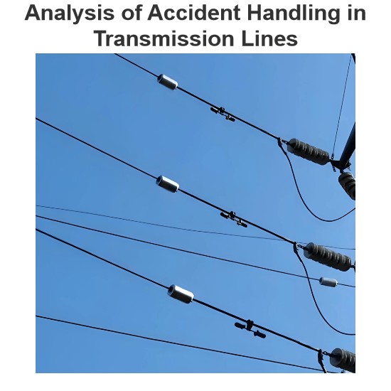 Analysis of Accident Handling in Transmission LinesAnalysis of Transmission Line Fault HandlingAs a fundamental component of the power grid, transmission lines are widely distributed and numerous, often exposed to diverse geographical and climatic conditions, making them highly susceptible to faults. Common causes include overvoltage, pollution flashover, insulation damage, tree encroachment, and external damage. Line tripping is one of the most frequent faults in power plant and substation operations, with fault types including single-phase-to-Leon09/04/2025
 -
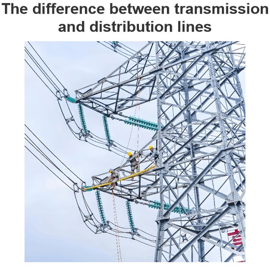 The difference between transmission and distribution linesTransmission lines and distribution lines are both used to carry electrical power from one location to another. However, they differ significantly in key aspects such as primary function, voltage levels, phase configuration, and conductor placement. These differences are essential for understanding their distinct roles in the power system.The Difference Between Transmission and Distribution Line is given below in the tabulated form.Electricity generation is a critical component of the power systEdwiin09/04/2025
 -
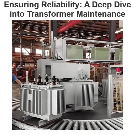 Ensuring Reliability: A Deep Dive into Transformer MaintenanceIntroductionElectric transformers are the backbone of modern power distribution systems, silently enabling the reliable delivery of electricity to homes, businesses, and industries. As these critical assets age and the demand for uninterrupted power grows, the importance of diligent transformer maintenance has never been greater. This essay explores the essential role of transformer maintenance, highlighting the value of proactive care, the impact of advanced diagnostic technologies, and the traVziman09/03/2025


