• Product
  • Suppliers
  • Manufacturers
  • Solutions
  • Free tools
  • Knowledges
  • Experts
  • Communities
Search


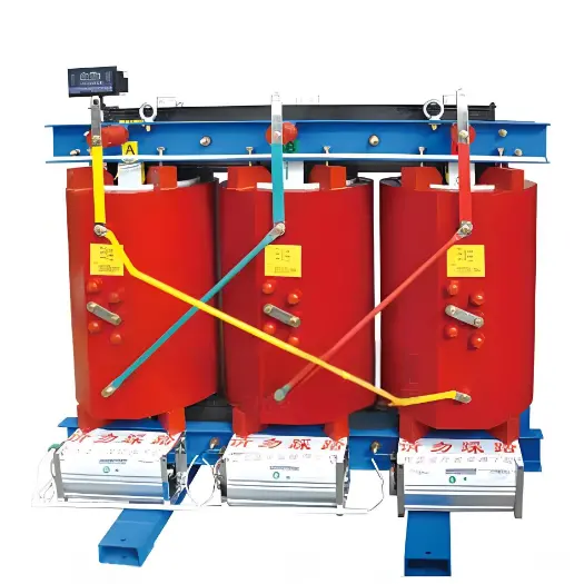
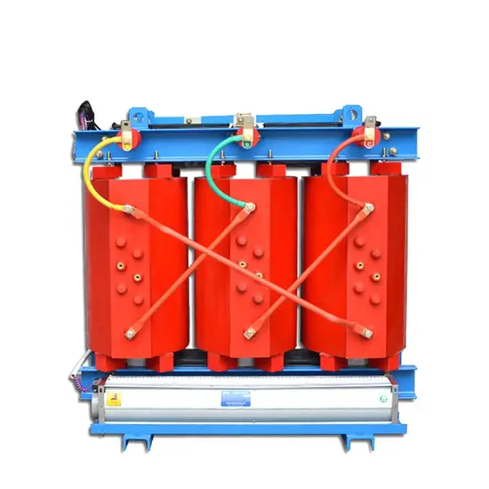
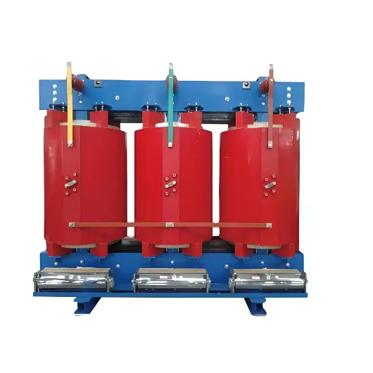
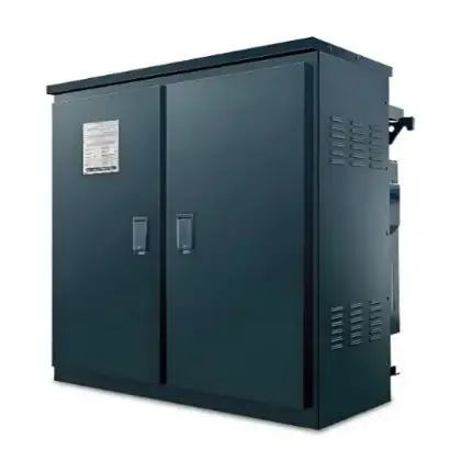
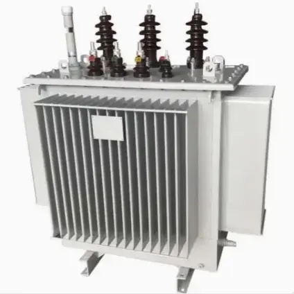
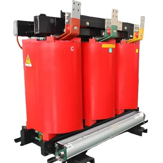
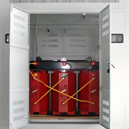
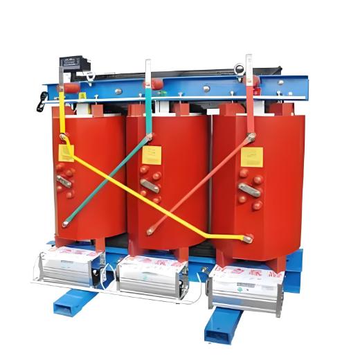
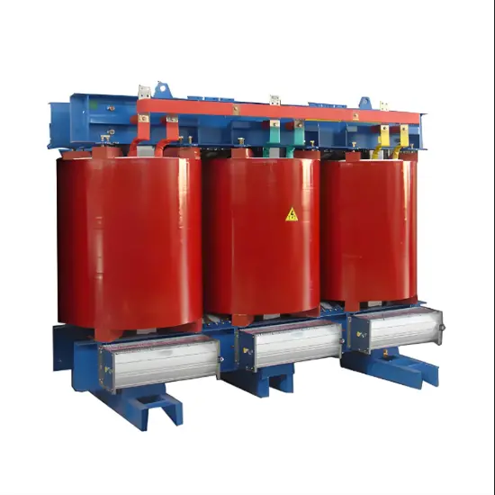
Resin-insulated Dry Type Transformer 800kVA 1000kVA 1250kVA 1600kVA 2000kVA 2500kVA

  • Resin-insulated Dry Type Transformer 800kVA 1000kVA 1250kVA 1600kVA 2000kVA 2500kVA
  • Resin-insulated Dry Type Transformer 800kVA 1000kVA 1250kVA 1600kVA 2000kVA 2500kVA

Key attributes

Brand Vziman
Model NO. Resin-insulated Dry Type Transformer 800KVA 1000KVA 1250KVA 1600KVA 2000KVA 2500KVA
Rated capacity 2500kVA
Voltage grade 10KV
Series SC(B)
Description

Description:

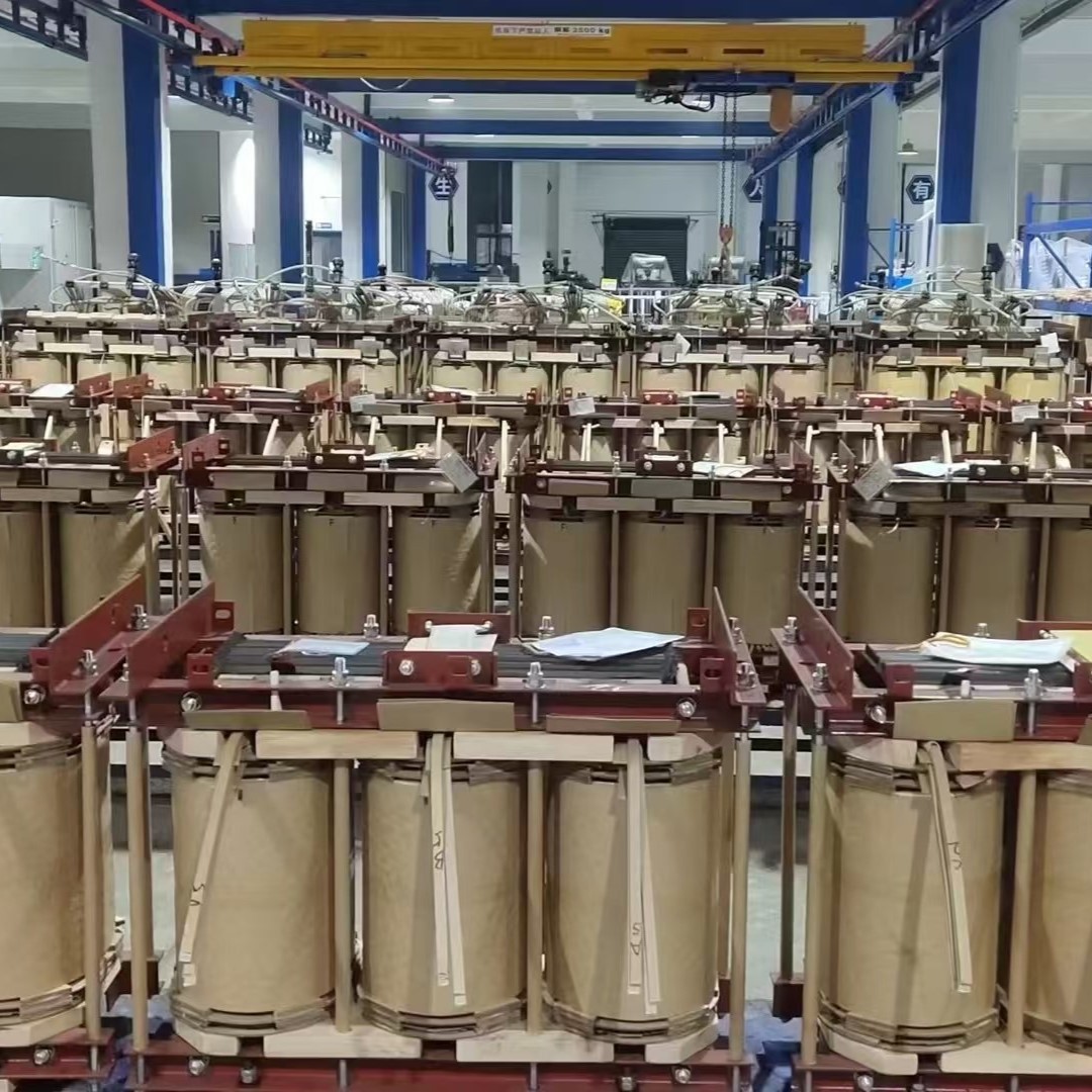
Foil Coil: Adopting the entire section of copper foil, together with the F-class turn insulation, low voltage winding is wound by the special low-voltage foil winding machine. The foil coil resolves problems such as large short-circuit stress, ampere turn unbalance, poor heat dissipation, existing the winding spiral angle and unsteady manual welding quality due to low voltage and large current coil. At the same time, the end of winding is treated with cast resin, solidification to make shape, moisture-proof and anti-fouling, the lead for copper bar is welded by argon arc welding automatically.Temperature Control Device: the transformer adopts BWDK series of signal thermometer. The temperature components are embedded in the upper half of the low-voltage coil, can detect and display the temperature of separate phase coil automatically and continuously, also have the functions of over-temperature alarm and trip.

Feature:

  • Flame retardant, non-pollution, it can be installed directly in the load center.

  • Maintenance-free, easy to be installed, low operating costs.

  • The enclosure can be of Good moisture resistance, transformer can be put into operation without pre-drying under 100% humidity in the normal operation.

  • Low loss, light weight and small volume, low noise, good dissipation of heat, it can be 150% rated load operation under forced air cooling conditions.

  • Equipped with a complete temperature protection control system to provide reliable protection for the safe operation of transformers.

  • High reliability. The results of checking for the products that has been put into operation show that the reliability index has reached the international advanced level.


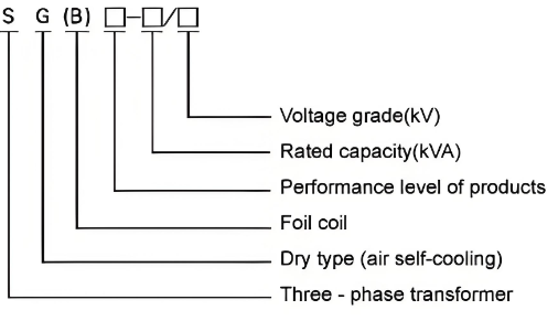
Model and Meaning:
企业微信截图_17230768291792.png

Parameter:

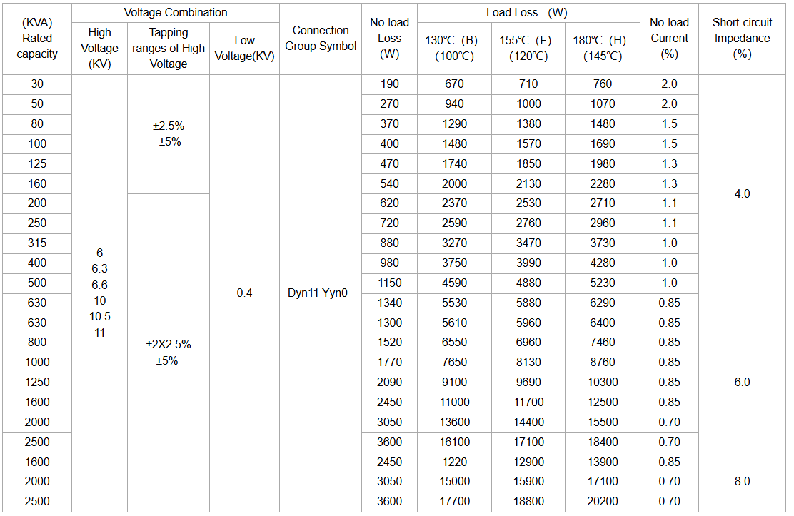
6kV, 10kV& 30kVA-2500kVA 

image.png

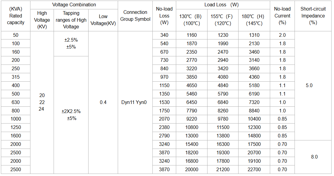
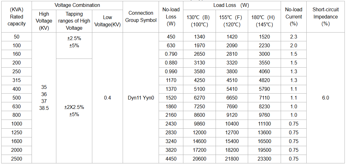
The load losses listed in the table are the values of the reference temperature for different insulation systems in parentheses; The load losses under other insulation system temperatures that are not included in the table should be according to their respective reference temperatures, the corresponding calculation is based on the"- 155 ℃ (F)" insulation system temperature data.

Notes: The Dimension and weight will be changed according to the requirements. 

 20kV & 50kVA-2500kVA 
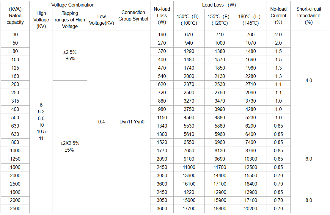
image.png

20kV & 50kVA-2500kVA

image.png

35kV & 50kVA-2500kVA

image.png

How resin-insulated dry-type transformers are cooled?

Natural Air Cooling (AN):

Natural air cooling is the most common cooling method, applicable to resin-insulated dry-type transformers with relatively low power. This method utilizes the natural convective air flow to dissipate heat.

Working Principle:

  • Air Convection: During the operation of the transformer, heat will be generated, which will cause the temperature of the surrounding air to rise. The hot air will ascend, and the cold air will flow in to replace it, thus forming natural convection.

  • Heat Sinks: To enhance the heat dissipation effect, the outer surface of the transformer is usually designed with heat sinks or cooling fins to increase the surface area and improve the heat dissipation efficiency.

  • Ventilation Holes: The casing of the transformer is designed with ventilation holes to ensure air circulation and further improve the heat dissipation effect.

Forced Air Cooling (AF):

Forced air cooling is applicable to resin-insulated dry-type transformers with relatively high power. It improves the heat dissipation efficiency by forcing air to flow with the help of fans.

Working Principle:

  • Fans: Fans are installed near the transformer. The fans blow the external cold air into the interior of the transformer to carry away the heat.

  • Air Duct Design: Air ducts are designed inside the transformer to ensure that the air can flow evenly through each heat-generating part, thus enhancing the heat dissipation effect.

  • Temperature Monitoring: Usually equipped with temperature sensors, it monitors the temperature of the transformer in real time. According to the temperature changes, it automatically controls the start and stop of the fans to achieve intelligent cooling.

Documentation Resource Library

Restricted
Vziman IEC/ ANSI Dry-Type Power transformer selection catalog
Catalogue
English
Consulting

Know your supplier

Online store
On-time delivery rate
Response time
100.0%
≤4h
Company overview
Workplace: 10000m² Total staff: 300 Highest Annual Export(usD): 150000000
Services
Business Type: Design/Manufacture/Sales
Main Categories: High Voltage Electrical Apparatus/Electric transformer
Related Products
Related Knowledges
  • How has g3 technology changed the global climate?
    The Alternative to SF6 for High Voltage ApplicationsRemoving Greenhouse Gases from the GridNineteen of the warmest years on record have occurred since 2000, where greenhouse gases (GHGs) are at the root cause of climate change. Sulfur hexafluoride (SF₆), an insulating gas used in high-voltage switchgear, is estimated to contribute 23,500 times more than carbon dioxide (CO₂) to the greenhouse effect and can remain in the atmosphere for 3,200 years. Previously, Power Generation and Transmission ut
    05/09/2026
  • Difference Between Maintenance Earthing Switches and Fast Earthing Switches?
    Maintenance earthing switches and fast earthing switches (FES) are two types of switches with distinct characteristics.Maintenance Earthing SwitchesThese are typically configured alongside the disconnectors on both sides of a circuit breaker. Their sole purpose is to provide safety grounding on both sides of the circuit breaker during equipment maintenance.Fast Earthing Switches (FES)These are positioned on the line side of the outgoing disconnector in an outgoing circuit. They serve two primary
    05/08/2026
  • SiC MOSFET Solid State Circuit Breakers for Low Voltage Protection
    1. Core Principle SummaryIn simple terms, its core principle can be summarized as a three-step AC-DC-AC conversion, with the key step being to increase the frequency first, then transform the voltage.2. Working PrincipleRectification:First, the input line-frequency AC power (e.g., 50 Hz or 60 Hz) is rectified into DC power using power electronic devices (such as IGBTs). This step converts low-frequency AC into stable DC, preparing it for subsequent processing.High-Frequency Chopping (Inversion):
    05/03/2026
  • Solid-State Circuit Breakers Set to Revolutionize Circuit Protection
    Custom modules built with SiC MOSFETs minimize the impacts of short circuits and overloadsNearly every electrical engineer has wondered at some point whether it is possible to design a non-mechanical circuit breaker. There are plenty of reasons for this line of thought: would it not be better to use semiconductors to interrupt faults or handle overload conditions?However, deeper investigation inevitably reveals major obstacles. For one thing, the breakdown voltage of familiar power devices is ar
    05/03/2026
  • 2025 Complete Guide to Solar Cell Selection-Scenario Adaptation
    Solar Panel – Comprehensive Guide to Solar Cell SelectionA systematic selection reference for photovoltaic engineers and technicians, covering technical principles, key parameters, application scenarios and development trends.Data baseline: 2024–2025 industrial mass-production levels (CPIA data)1. The Role of Solar Cells in Photovoltaic SystemsMore than 90% of the conversion efficiency and power generation performance of PV modules are determined by solar cells. As the core semicondu
    05/03/2026
  • Technological Evolution of Silicon Carbide (SiC) Based DC Solid-State Circuit Breakers
    1. Introduction: Protection Challenges in the DC Distribution EraAs the global energy transition accelerates, DC microgrids, high-voltage DC (HVDC) power supplies for data centers, and large-scale energy storage systems have become critical components of power systems. However, DC systems lack a natural zero-crossing point and possess extremely low system impedance, leading to a rapid rate of rise of fault current (di/dt). Traditional mechanical circuit breakers, limited by millisecond-level ope
    04/25/2026
Related Free tools
Send inquiry
+86
Click to upload file
Download
Get the IEE Business Application
Use the IEE-Business app to find equipment, obtain solutions, connect with experts, and participate in industry collaboration anytime, anywhere—fully supporting the development of your power projects and business.