| Brand | Schneider |
| Model NO. | PMSet U-Series: Three-Phase Recloser |
| Rated voltage | 15kV |
| Series | PMSet U |
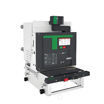
Overview
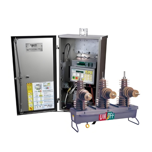
The PMSet U-Series circuit breaker is controlled and monitored by either the COMPACT or ULTRA PowerLogic ADVC Controller (ADVC). Enclosed in a stainless steel or mildsteel enclosure coated with zinc rich epoxy and special powder paint system PowerLogic ADVC provides an electronic controller with Operator Interface (O.I.) that monitors the circuit breaker and provides protection, measurement, control, and communication functions. Connected via a control cable, the switchgear and PowerLogic ADVC can form a remotely controlled and monitored
ACR.


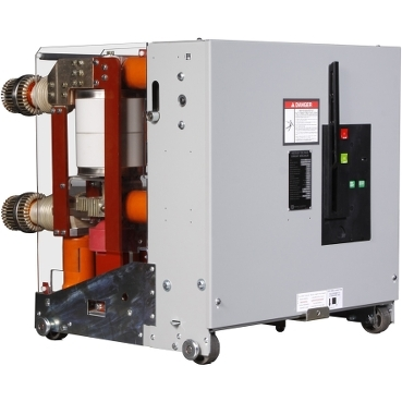
Function
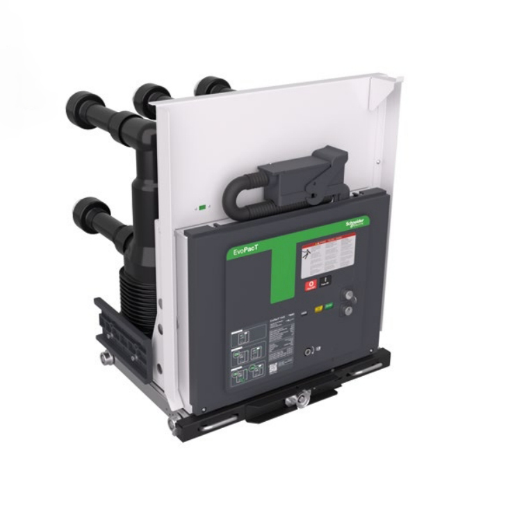
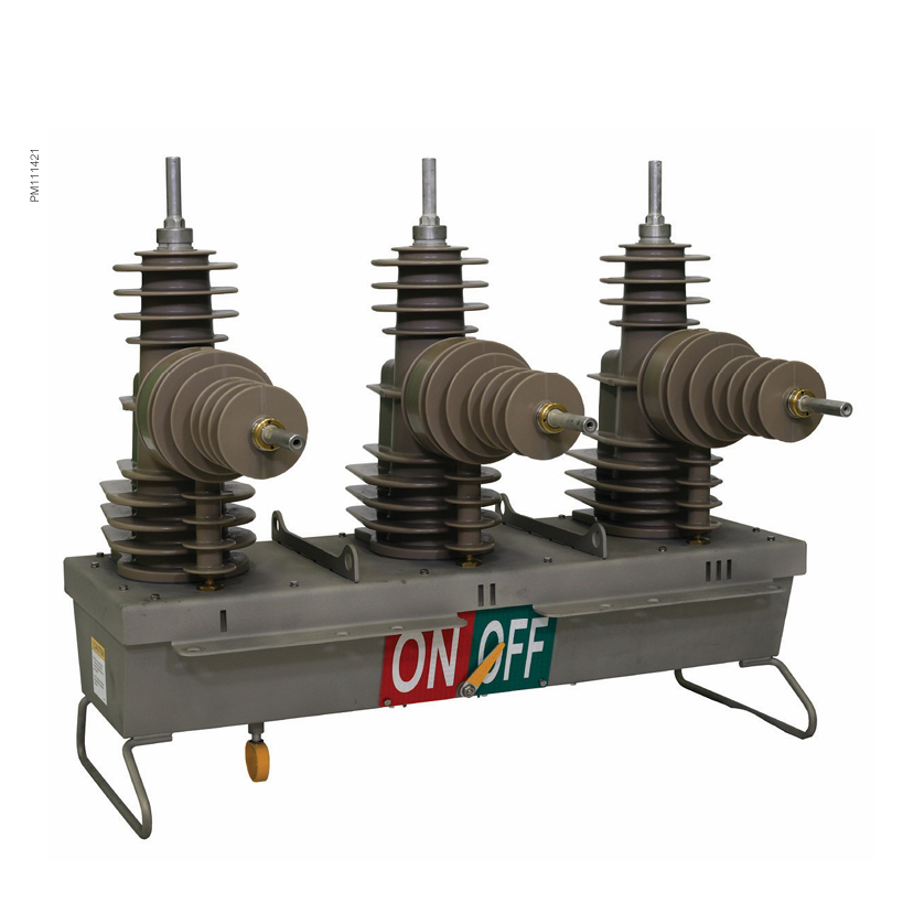
The switchgear is operated by a magnetic actuator that produces an opening and closing action. Switching occurs when a controlled pulse is sent to the open/close actuator from storage capacitors in the PowerLogic ADVC. When closed, the switch is latched magnetically. Spring loaded push-rods provide contact loading on the interrupters. A Current Transformer (CT) and two Capacitive Voltage Transformer (CVT) are molded to the epoxy pole. These are monitored by the PowerLogic ADVC for protection, remote monitoring, and display. An auxiliary voltage supply of 115/230 V AC is required to power the control unit. Where this is inconvenient, an additional voltage transformer can be provided. The recloser is provided with terminal nemapad connectors or an optional cable clamp. Mounting brackets for surge arresters are optionally available. The switchgear contact position is shown by a large, clearly visible external pointer.
The main tank is equipped with a manual trip lever that can be operated from ground level by a hook stick which performs open and lockout simultaneously. The mechanical lever electronically inhibits both local and remote closing. The position of the lever is indicated to the PowerLogic ADVC by an associated micro- switch. The manual trip ring remains in the down position until physically returned to the normal position by the operator. The PowerLogic ADVC interfaces to the switchgear via the control cable and connects to the Switch Cable Entry Module (SCEM) in the base of the tank via a covered plug/socket sealing arrangement on both the PowerLogic ADVC and the switchgear. The SCEM uses non-volatile memory to store the relevant calibration data, ratings, and number of operations. The SCEM also provides the first stage of electrical isolation and shorting electronics too short the CTs and CVTs in the event the control cable is disconnected while current is flowing through the switchgear.
Recloser Specifications


ADVC Overview
Advanced protection, data logging, and communications capabilities are made possible by the technology housed inthe PowerLogic ADVC. It has been designed especially for outdoor pole mounted operation and is typically mounted low on the pole for ease of access by operation personnel.
ADVC Functions
With a cubicle designed to minimize temperature rise from solar heating, the stainless steel or mildsteel enclosure, or enclosed in a mild steel enclosure coated with zinc rich epoxy and special powder paint system is used to mount the Control and Protection Enclosure (CAPE), Power Supply Unit (PSU),customer accessories, and Operator Interface.The PowerLogic ADVC Series incorporates the functions of a multi-function protection relay, a circuit breaker controller, a metering unit, and a remote terminal unit.Batteries are carefully located underneath these modules to help avoid overheating so that a battery life of up to 5 years(1) can be achieved. A vandal resistant lockable stainless steel or mild steel door, sealed with a rubber gasket,provides access to the operator interface. Vents are screened against verminentry and the electronic parts are enclosed in a sealed die-cast enclosure which helps protect them from the entry of moisture and condensation for a long lifetime.
The COMPACT cubicle is suitable for temperatures from -10 to 50 °C, while the option of a battery heater in the ULTRA extends its operating temperature range from -40 to 50 °C.A built-in microprocessor controlled power supply provides uninterrupted operation of not only the circuit breaker and controller, but also the communications radio or modem. These accessories are connected to a built-in user programmable radio power supply. Therefore, no other power supplies are required for connection into your SCADA or Distribution Automation System.Due to careful design the efficiency of the parts is high, allowing a lead-acid battery hold-up time of up to 46 hours(2). The LiFePO4 Battery of the controller can offer 43 hours of hold up time(3).The architecture used has the advantage that the circuit breaker operation is independent of the high voltage supply, relying on a set of capacitors charged by the auxiliary supply.Due to sophisticated power supply management techniques, a circuit breaker operation will operate when attempted, and alarms are raised over the telemetry when auxiliary power is lost. Communications equipment can be mounted within the PowerLogic ADVC cubicle. RS-232 and Ethernet TCP/IP are provided asstandard to support your communications needs.
ADVC Specifications
The PowerLogic ADVC series is available in two models:
• ULTRA
• COMPACT
The following table outlines some of the differences between the two models: