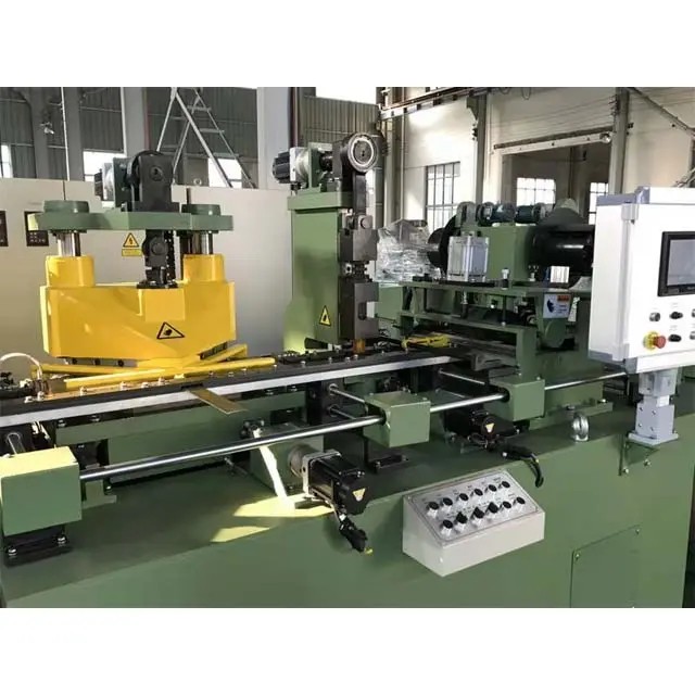
• PRJ double winding Copper Strip Foil Winding Machine for machinery industry
  • PRJ double winding Copper Strip Foil Winding Machine for machinery industry
PRJ double winding Copper Strip Foil Winding Machine for machinery industry
$143400.00
Model
PRJ-1600D
PRJ-1600S
PRJ-1400S
PRJ-1400D
PRJ-1200D
PRJ-1200S
PRJ-1000D
PRJ-1000S
PRJ-600D
PRJ-600S
PRJ-800
PRJ-800S
Basic info
Brand Wone
Model NO. PRJ double winding Copper Strip Foil Winding Machine for machinery industry
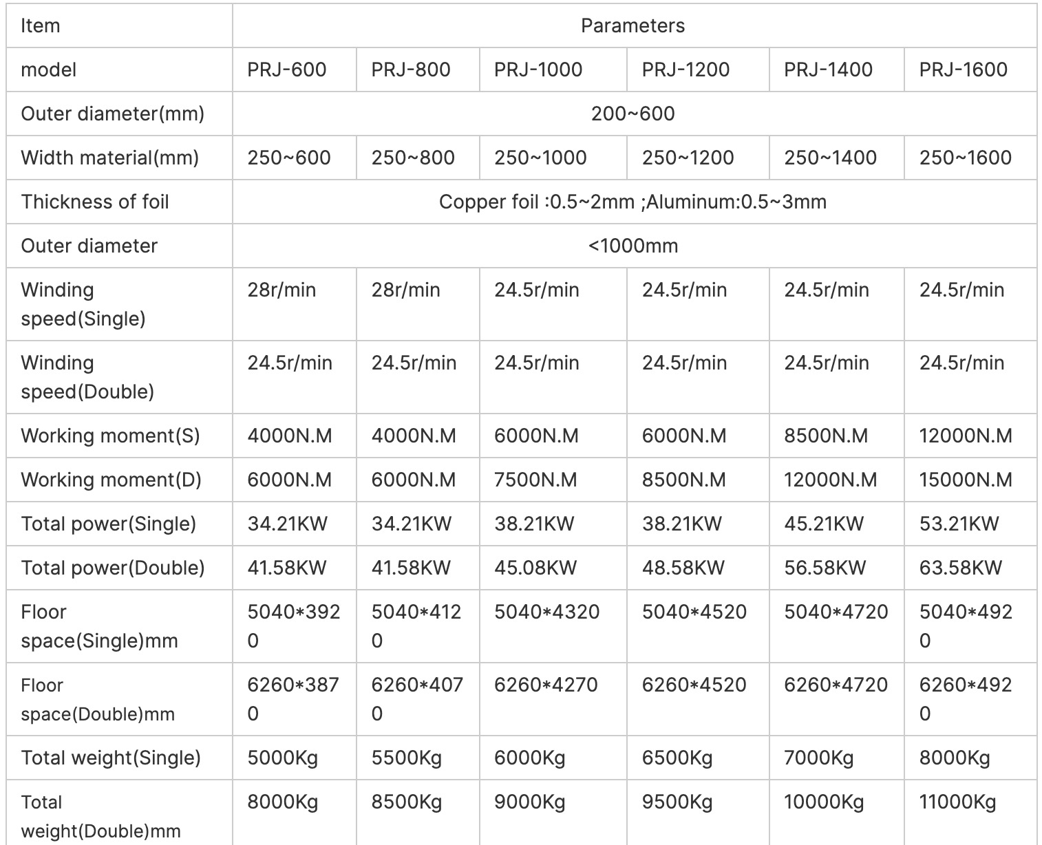
Outer diameter(mm) 200~600mm
Width material(mm) 250~1600mm
Thickness of foil 0.5-3mm
Winding speed 24.5r/min
Working moment 15000N.M
Total power 63.58KW
Volume Number Double
Series PRJ
Product Detail

Description

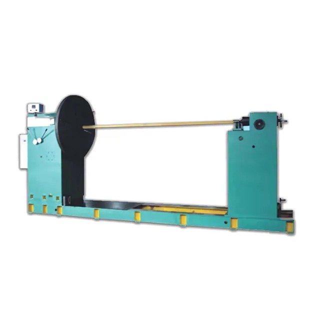
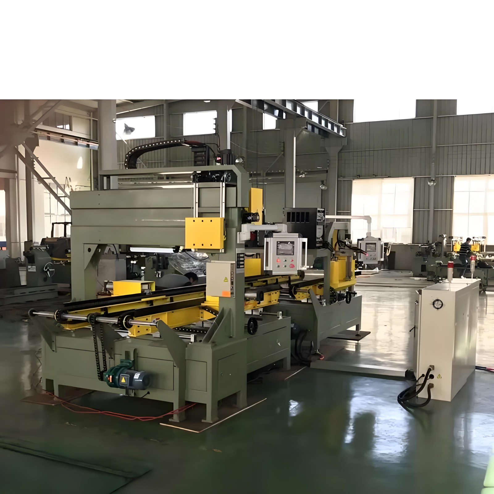
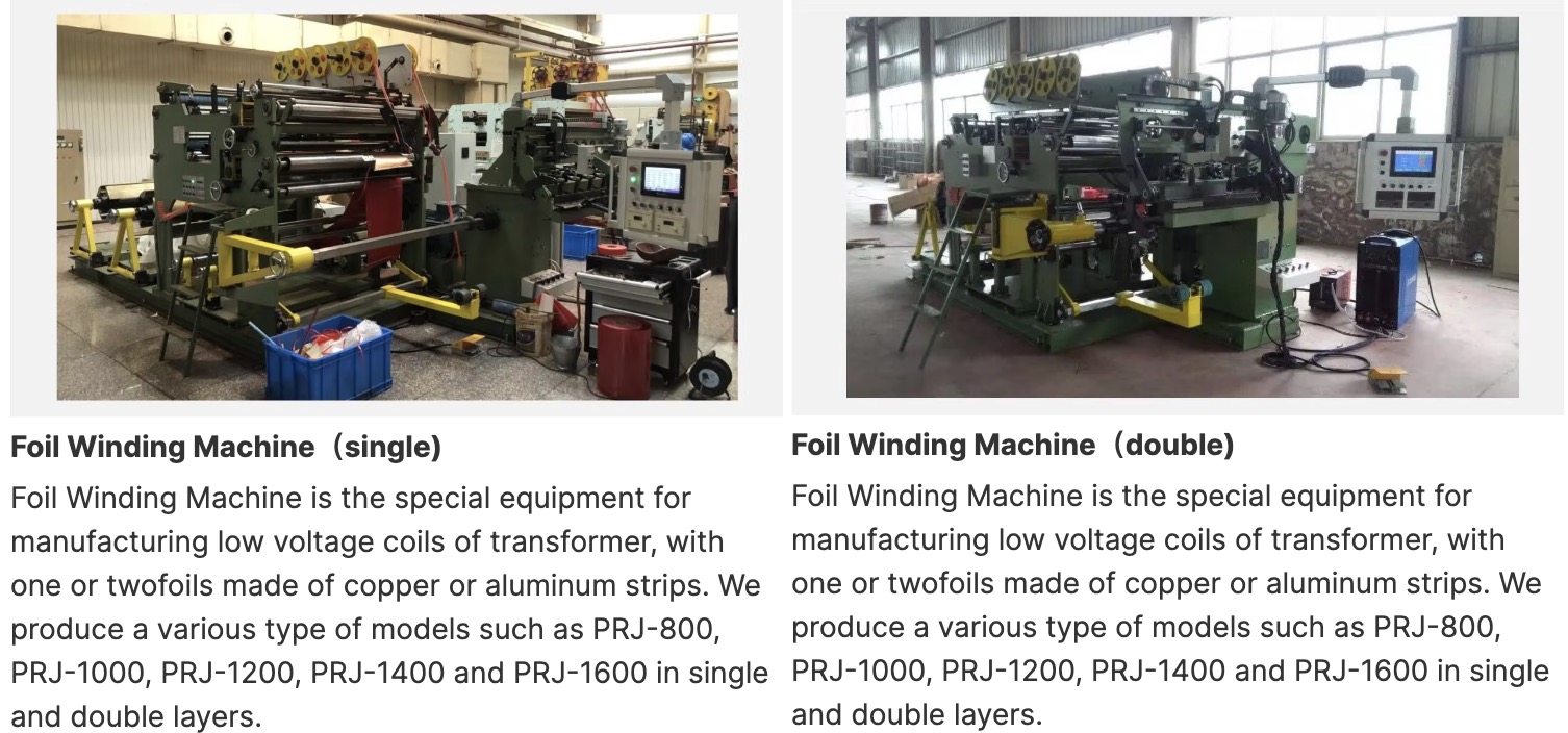
The PRJ Foil Winding Machine is a foil coil winding system which is applicable for transformer and electrical industry. Foil coil is made of copper or aluminum foil of different thickness as conductor, with wide-band insulating material as layer insulation, and narrow-band insulating material as end insulation. The winding is completed by the foil winding machine and the coil is formed. Meanwhile, the welding of the inner and outer leads of the coil and binding of outer surface are completed. Double layer foil winding machine can be used to foil with narrow strips and winding into a wide foil coil or can support a thin foil strip with two  layers of thick foil coil. It can provide enough support to produce foil coil conforming to the requirements of the specification with the functions of the equipment. This machine is a necessary equipment for production of such electrical products.

 Composition

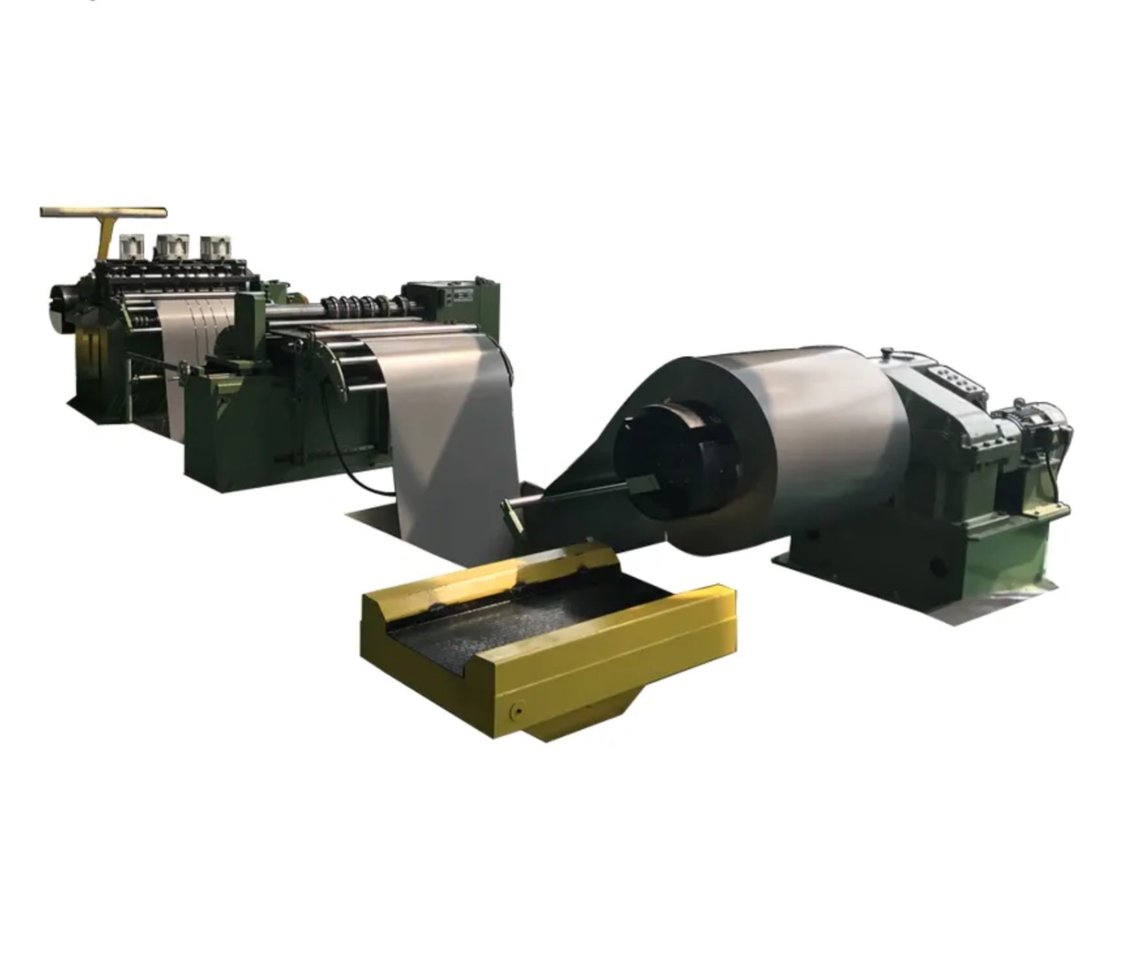
l● De-coiler of foil coil and foil offset regulating system

l● Foil edge burr remover and clean device

l● Foil feeding mechanism 

l● Foil offset regulating sensing system

l● Electrical tensioning device

l● Foil sheet shearing unit 

l● De-coiler for layer insulation 

l● Layer insulation edge cutting mechanism

l● Welding unit

l● Foil winding system 

l● End insulation strip wrapping system 

l● Discharge trolley 

l● Wound coil pressing device

l● Electrical control system

Specifications
1719538795338.jpg

1719538854188.jpg

Know your supplier
Wone
Main Categories
High Voltage Electrical Apparatus/Low Voltage Electrical Apparatus/Wire cable/Instrument meters/New energy/Tester/Production equipment/Generator/Electrical fittings/Integrated Electrical Equipment
Business Type
Design/Manufacture/Sales
Highest Annual Export (USD)
$50,000,000
Professional Experience
1 years
Workplace
65666m²m²
占位
占位
Related Products
Related Knowledges
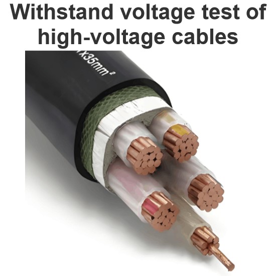
Withstand voltage test of high-voltage cables
Withstand voltage test is an insulation test, but it is a destructive test that can reveal insulation defects difficult to detect in non-destructive testing.The test cycle for high-voltage cables is three years, and it must be conducted after non-destructive tests. In other words, the withstand voltage test is performed only after all non-destructive tests have been passed.Most high-voltage cables used today are cross-linked polyethylene (XLPE) cables, which can have large cross-sections and cov
Oliver Watts
09/03/2025
Analysis of Abnormal Causes of High-Voltage Cable Grounding Circulation and Typical Cases
I. Introduction to Cable Grounding Loop CurrentCables rated 110 kV and above use a single-core structure. The alternating magnetic field generated by the operating current induces a voltage on the metallic sheath. If the sheath forms a closed circuit through the earth, a grounding loop current will flow on the metallic sheath. Excessive grounding loop current (loop current exceeding 50 A, more than 20% of the load current, or a ratio of maximum-to-minimum phase current greater than 3) not only a
Felix Spark
09/03/2025
Considerations and Recommendations for Flame-Retardant Selection of High-Voltage Cables
1.Flame-Retardant Cable Classification StandardsThe flame-retardant standard system is divided into two main categories. The first category follows the "Classification of Burning Behavior for Electric and Optical Fiber Cables" GB 31247. Cables complying with this standard system are widely used in densely populated areas such as high-speed railways and subways. This standard imposes strict requirements on parameters such as smoke density, heat release, and total smoke production, and cables typi
James
09/03/2025
Repair of high-voltage cable metallic sheaths
I. Functions of Metallic Sheaths and Necessity of RepairThe metallic sheath of high-voltage cables is a metal shielding structure laid outside the insulation layer, including types such as lead sheaths, aluminum sheaths, and steel wire armor. Its core functions include mechanical protection (resisting external impact and compression), electrochemical corrosion protection (isolating moisture and soil pollutants), electromagnetic shielding (reducing electromagnetic interference to the environment)
Felix Spark
09/03/2025
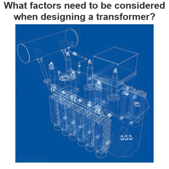
What factors need to be considered when designing a transformer?
Transformer design is a complex process that requires consideration of multiple factors to ensure safe and efficient operation. In addition, compliance with international and local regulations is essential to guarantee that transformers meet safety and performance standards. Below are key factors to consider in transformer design and the relevant regulations to follow:Transformer Design Factors: Voltage and Frequency: Determine the input and output voltage levels and the operating frequency. The
Vziman
09/02/2025
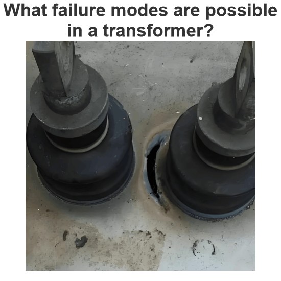
What failure modes are possible in a transformer? How to identify and fix these failures?
Transformers are critical components in power systems, and various failure modes can affect their operation. Timely identification and resolution of these failure modes are essential to prevent costly downtime and ensure system reliability. Below are some common transformer failure modes, along with methods to identify and address them: Insulation FailureIdentification: Insulation failure leads to decreased insulation resistance, which can be detected through insulation resistance testing (megge
Edwiin
09/02/2025
×
Inquiry
Download
IEE-Business is dedicated to serving the personnel in the global power industry.
Join IEE-Business, not only can you discover power equipment and power knowledge, but also canhnd like - minded friends!