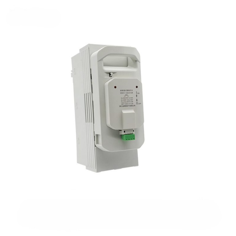
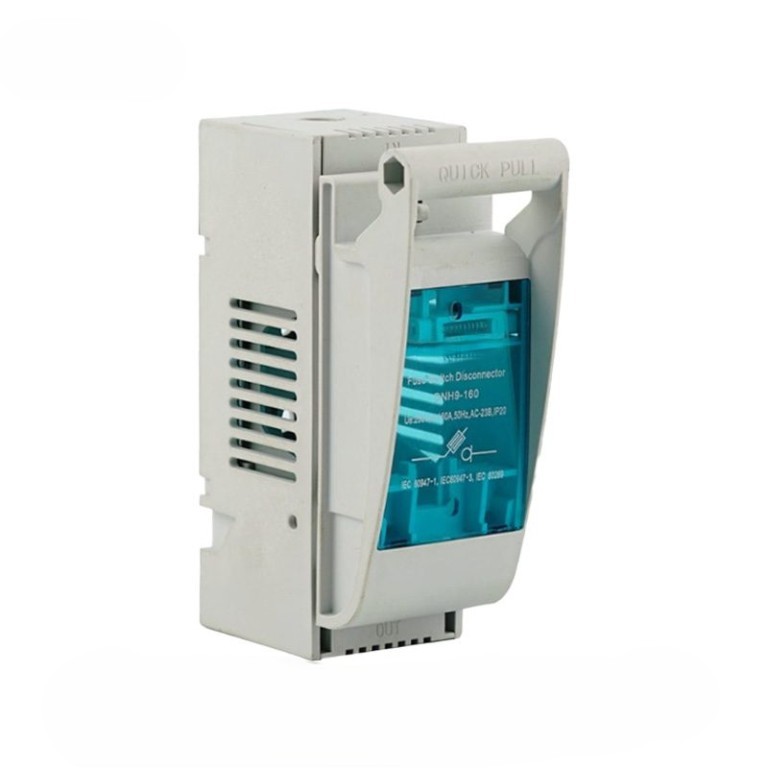
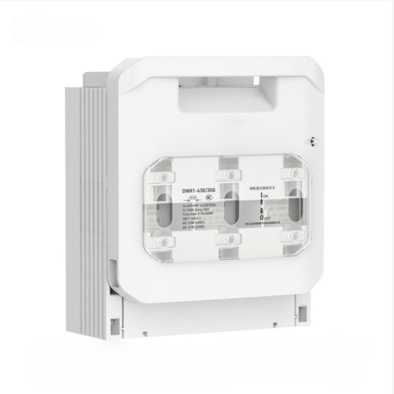
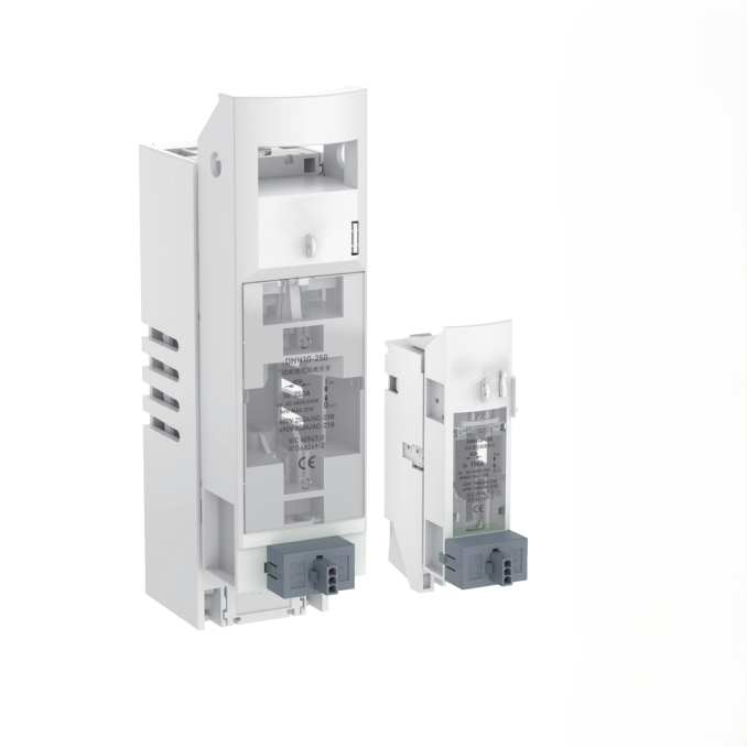
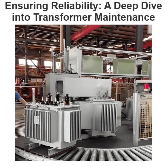
• HD11F, HS11F series single throw and double throw protective knife switches
  • HD11F, HS11F series single throw and double throw protective knife switches
  • HD11F, HS11F series single throw and double throw protective knife switches
HD11F, HS11F series single throw and double throw protective knife switches
discuss personally
Model
HS11F-100-1000A
HD11F-100-1500A
Basic info
Brand Switchgear parts
Model NO. HD11F, HS11F series single throw and double throw protective knife switches
Rated normal current 100-1000A
number of poles 3P,4P
Series HD11F, HS11F
Product Detail

Applicable scope

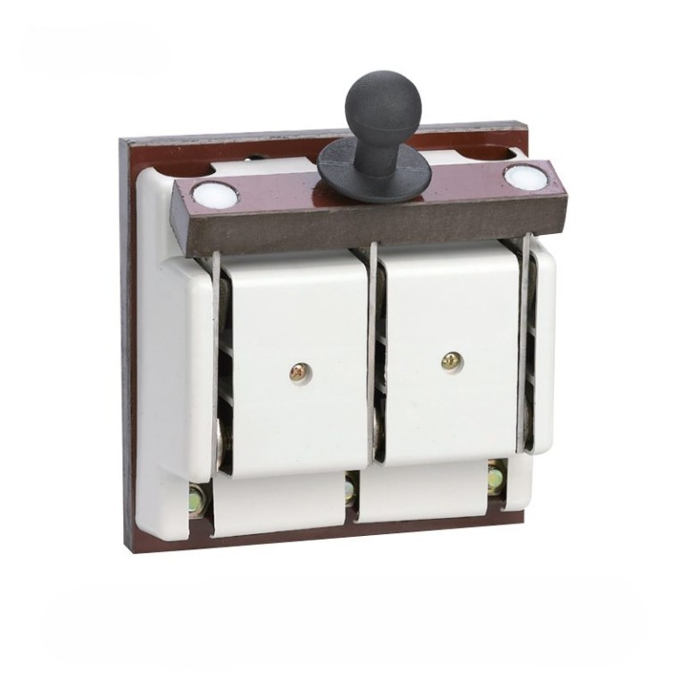
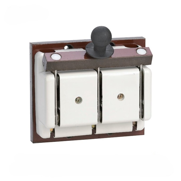
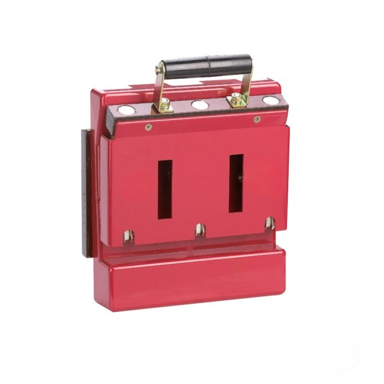
The HD11F and HS11F series single throw and double throw protective knife switches are newly developed products derived from HD11 and HS11 by our company.

They are ideal substitutes for HD11 and HS11, greatly improving personal safety protection performance and preventing accidental electric shock.

This series of products is mainly used in low-voltage distribution equipment for infrequent manual connection, disconnection, and isolation of power supply.

This product complies with the GB14048.3 IEC60947-3 standard.

Normal working and installation conditions

The ambient air temperature shall not be higher than+40 ℃ and not lower than -5 ℃

The elevation of the installation site shall not exceed 2000m

Humidity: When the maximum temperature is+40 ℃, the relative humidity of the air does not exceed 50%. Higher relative humidity can be allowed at lower temperatures, such as reaching 90% at 20 ℃. Corresponding measures should be taken for occasional condensation caused by temperature changes

The pollution level of the surrounding environment is Level 3

The switch should be installed in a place without significant shaking, shock vibration, and rain or snow invasion. The same installation location should have no explosive hazardous medium, and there should be no gas or dust in the medium that is sufficient to corrode metal and damage insulation.protective knife switches

Main technical parameters

Agreed heating current (A) 100 200 400 600 1000 1500
Rated working current (A) 100 200 400 600 1000 1500
Rated insulation voltage (V) 1000 1000 1000 1000 1000 1000
Rated working voltage (V) 400/690 400/690 400/690 400/690 400/690 400/690
Mechanical life (times) 8000 8000 5000 5000 3000 3000
Short time withstand current for 1 second(KA) 10 10 15 20 25 35
Operating force (N) ≤300 ≤300 ≤400 ≤400 ≤450 ≤450

Know your supplier
Switchgear parts
VoltEdge Solutions​​ specializes in manufacturing premium ​​MV switchgear accessories​​ for global power distribution systems. Our product range includes circuit breaker modules, disconnector spares, and surge arrestors, engineered for ​​24kV+ substations​​ and renewable energy plants. With ISO-certified production and 24/7 technical support, we ensure ​​reliability, compliance​​ with IEC standards, and rapid global supply.
Main Categories
Electrical fittings/Equipment Parts/Low Voltage Electrical Apparatus
Business Type
Sales
Highest Annual Export (USD)
$300000000
Professional Experience
1 years
Workplace
1000m²
占位
占位
Related Products
Related Knowledges
Ensuring Reliability: A Deep Dive into Transformer Maintenance
IntroductionElectric transformers are the backbone of modern power distribution systems, silently enabling the reliable delivery of electricity to homes, businesses, and industries. As these critical assets age and the demand for uninterrupted power grows, the importance of diligent transformer maintenance has never been greater. This essay explores the essential role of transformer maintenance, highlighting the value of proactive care, the impact of advanced diagnostic technologies, and the tra
Vziman
09/03/2025
How does a transformer work?
Transformer Operation PrincipleA transformer is an electrical device that operates on the principle of electromagnetic induction to transfer electrical energy from one circuit to another. It enables the adjustment of voltage levels within an alternating current (AC) system, either stepping up (increasing) or stepping down (decreasing) voltage while maintaining the same frequency.Working Principle:Basic ComponentsA transformer consists of two coils, known as windings—the "primary winding" connect
Rockwell
09/03/2025
Constant testing of high-voltage cable lines
1. Definition of High-Voltage Cable Line Constant TestingHigh-voltage cable line constant testing refers to the systematic measurement, using specialized instruments, of electrical parameters such as resistance, inductance, capacitance, and conductance before a cable line is commissioned or after major maintenance. The aim is to obtain fundamental data characterizing the electromagnetic properties of the cable, serving as a critical testing phase that provides accurate parameter support for powe
Oliver Watts
09/03/2025
Technical Analysis of 220 kV High-Voltage Cable Construction in Winter
1.Work Environment Requirements and Safeguard MeasuresBased on technical requirements for cable equipment storage, laying, transportation, laying, transposition, testing, and cable terminations, the project owner and construction units have conducted extensive trials and implemented protective measures regarding ambient temperature, humidity, bending radius, traction control, and route optimization. These measures ensure high-voltage cable quality and on-site safety under harsh winter conditions
James
09/03/2025
Withstand voltage test of high-voltage cables
Withstand voltage test is an insulation test, but it is a destructive test that can reveal insulation defects difficult to detect in non-destructive testing.The test cycle for high-voltage cables is three years, and it must be conducted after non-destructive tests. In other words, the withstand voltage test is performed only after all non-destructive tests have been passed.Most high-voltage cables used today are cross-linked polyethylene (XLPE) cables, which can have large cross-sections and cov
Oliver Watts
09/03/2025
Analysis of Abnormal Causes of High-Voltage Cable Grounding Circulation and Typical Cases
I. Introduction to Cable Grounding Loop CurrentCables rated 110 kV and above use a single-core structure. The alternating magnetic field generated by the operating current induces a voltage on the metallic sheath. If the sheath forms a closed circuit through the earth, a grounding loop current will flow on the metallic sheath. Excessive grounding loop current (loop current exceeding 50 A, more than 20% of the load current, or a ratio of maximum-to-minimum phase current greater than 3) not only a
Felix Spark
09/03/2025
×
Inquiry
Download
IEE-Business is dedicated to serving the personnel in the global power industry.
Join IEE-Business, not only can you discover power equipment and power knowledge, but also canhnd like - minded friends!