| Brand | Switchgear parts |
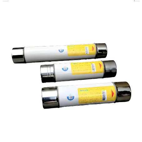
| Model NO. | AR Fuses DNT-O1J Series Semiconductors Equipment Protection Fuses |
| Rated voltage | AC 1000V |
| Rated normal current | 630-1500A |
| Breaking capacity | 100kA |
| Series | DNT-O1J |
Semiconductor fuses are designed to protect electronic components from excessive current that can cause damage or create a safety hazard. They are a critical element in power management and circuit protection. However, like all components, they can fail, and their failure modes can be broadly categorized as follows:
1.Overload Failures: The most common failure mode for a fuse is an overload condition where the current exceeds the fuse’s rated capacity. This is the intended operation—a fuse should “blow” or open the circuit under overload conditions to prevent damage to the circuit components.
2.Fatigue Failures: Over time, the fuse element may degrade due to thermal cycling or repeated stress from current surges that don’t quite reach the level needed to blow the fuse. This can eventually lead to a fatigue failure where the fuse blows at a lower current than rated.
3.Environmental Failures: Exposure to high temperatures, moisture, or corrosive environments can degrade the fuse materials, leading to premature failure.
4.Manufacturing Defects: Defects such as impurities in the fuse element, improper end cap attachment, or incorrect sizing can cause a fuse to fail prematurely or not operate as intended.
5.Improper Selection or Installation: If a fuse is not properly selected for its application, it may fail to operate correctly. For example, using a fuse with a rating too close to the normal operating current can lead to nuisance tripping, while a fuse with too high a rating may not protect the circuit adequately.
6.Voltage Transients: Spikes or surges in voltage can cause a current increase that may blow the fuse, even if the surge is very brief.
Proper Sizing: Ensure that fuses are correctly sized for the circuit they are protecting. The fuse should have a current rating higher than the normal operating current but lower than the current that could damage the circuit components.
Environmental Protection: Use fuses with the appropriate environmental rating for the application, and if necessary, add additional protection against moisture, temperature extremes, or corrosive substances.
Quality Control: Source fuses from reputable manufacturers that adhere to strict quality control standards to minimize the risk of manufacturing defects.
Correct Installation: Follow the manufacturer’s guidelines for fuse installation, including proper mounting and contact with fuse holders, to avoid issues related to loose connections or improper contact pressure.
Cycling Durability: For applications with frequent current surges, select fuses designed to withstand a larger number of cycles.
Surge Protection: Use additional surge protection devices in conjunction with fuses to handle voltage transients and spikes, such as metal oxide varistors (MOVs), transient voltage suppression (TVS) diodes, or surge arresters.
Routine Inspection: Implement a routine inspection and maintenance program to check for signs of fuse degradation or environmental damage.
By understanding the common failure modes of semiconductor fuses and taking steps to prevent them, the reliability of electronic systems can be significantly improved, reducing downtime and maintenance costs.
The specific compatible cabinets and models are as follows: photovoltaic combiner cabinet, energy storage converter cabinet, distributed photovoltaic grid connected cabinet, and storage integration cabinet etc.
| Product model | Size | Rated voltage V | Rated current A | Rated breaking capacity kA |
| DNT1-01J-160 | 1 | AC 1000 | 160 | 100 |
| DNT1-01J-200 | 200 | |||
| DNT1-01J-250 | 250 | |||
| DNT1-01J-315 | 315 | |||
| DNT1-01J-350 | 350 | |||
| DNT1-01J-400 | 400 | |||
| DNT1-01J-450 | 450 | |||
| DNT1-01J-500 | 500 | |||
| DNT1-01J-550 | 550 | |||
| DNT1-01J-630 | 630 | |||
| DNT2-01J-350 | 2 | 350 | ||
| DNT2-01J-400 | 400 | |||
| DNT2-01J-450 | 450 | |||
| DNT2-01J-500 | 500 | |||
| DNT2-01J-550 | 550 | |||
| DNT2-01J-630 | 630 | |||
| DNT2-01J-710 | 710 | |||
| DNT2-01J-800 | 800 | |||
| DNT3-01J-630 | 3 | 630 | ||
| DNT3-01J-710 | 710 | |||
| DNT3-01J-800 | 800 | |||
| DNT3-01J-900 | 900 | |||
| DNT3-01J-1000 | 1000 | |||
| DNT3-01J-1100 | 1100 | |||
| DNT3-01J-1250 | 1250 | |||
| DNT3-01J-1400 | 1400 | |||
| DNT3-01J-1500 | 1500 |