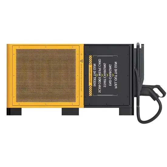
| Brand | Rw Energy |
| Model NO. | High-Power Double Gun DC EV Charging Station |
| Rated Output Rating | 400kW |
| Output Voltage | DC 200-1000V |
| Power Conversion Efficiency | ≥95% |
| Connector Options | CHAdeMO |
| Cable Length | 5m |
| Input Voltage | 380V |
| Series | WZ08 |
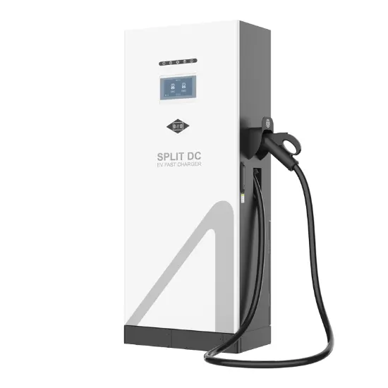
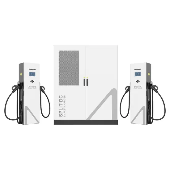
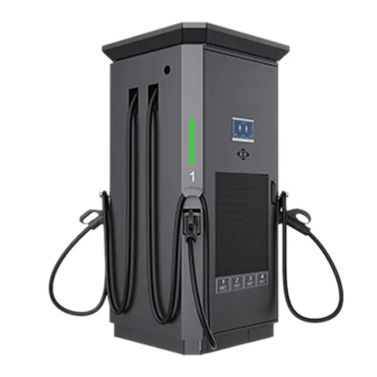
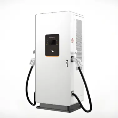
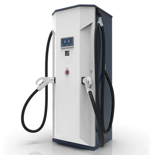
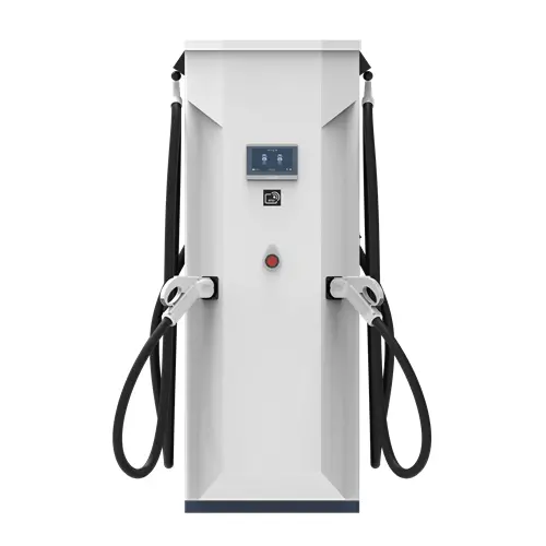
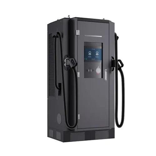
Product Overview
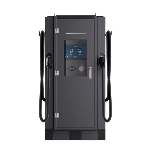
Tailored for commercial complex parking hubs, enterprise parks, gas station energy stations, urban public charging points, and operator network layouts, this pile supports expandable power up to 400kW and dual-gun simultaneous charging. Covering GBT/CCS2/CCS1/CHAdeMO/NACS connectors, it's compatible with domestic/foreign new energy vehicles. It connects to OCPP and mainstream domestic platforms (State Grid, YKC, Xiao Ju) for standalone/commercial use. Equipped with a 7-inch touch screen, RFID, it features ≥96% peak efficiency, air cooling, -30°C~75°C operating temperature, and a compact design for easy installation.
Key Features
Expandable Power: Up to 400kW, adapting to growing demand without full equipment replacement.
Dual-Gun Simultaneous Charging: Doubles throughput, reducing user queuing time.
Multi-Protocol Compatibility: Connects to OCPP and domestic mainstream platforms, flexible for standalone/commercial use..
High Efficiency: Peak efficiency ≥96%, reducing energy loss and operator costs.
Flexible Operation & Payment: 7-inch touch screen, RFID.
Stable Air-Cooled Design: Low failure rate, adaptable to -30°C~75°C harsh environments.
Comprehensive Safety: Overvoltage/lightning/overcurrent/leakage protection + emergency stop button.
Technical Parameters
Category |
specifications |
Data parameters |
|||||||||
Product Model |
WZ08-60kW |
WZ08-120kW |
WZ08-180kW |
WZ08-240kW |
WZ08-320kW |
WZ08-400kW |
|||||
Appearance structure |
Dimensions (L x D x H) |
745mm x 630mm x 1750mm |
700mm x 700mm x 1900mm |
||||||||
Weight |
360kg |
440kg |
|||||||||
Length of charging cable |
5m |
||||||||||
Connectors |
GBT,CCS2,CCS1,CHAdeMO,NACS |
||||||||||
Electrical indicators |
Input Voltage |
400VAC / 480VAC (3P+N+PE) |
|||||||||
Input frequency |
50/60Hz |
||||||||||
Output Voltage |
200 - 1000VDC |
||||||||||
Output current |
0-250A |
0-300A |
|||||||||
rated power |
600kW |
120kW |
180kW |
240kW |
320kW |
400kW |
|||||
Efficiency |
Peak Power≥96% |
||||||||||
Power factor |
>0.98 |
||||||||||
functional design |
Communication protocol |
OCPP 1.6J (State Grid Corporation of China, YKC, Xiao ju and other operating platforms.) |
|||||||||
Display |
7" LCD with touch screen |
||||||||||
Access Control |
RFID: ISO/IEC 14443A/B / POS machine (Optional) |
||||||||||
Communication |
WIF I/ Ethernet / 3G/4G Modem (Optional) |
||||||||||
Power Electronics Cooling |
Air Cooled |
||||||||||
work environment |
Operating temperature |
-30°C to 75°C |
|||||||||
Working / Storage Humidity |
≤95% RH / ≤99% RH (Non-condensing) |
||||||||||
Altitude |
<2000m |
||||||||||
Ingress Protection |
IP54 / IK10 |
||||||||||
safety design |
Safety protection |
Overvoltage protection, lightning protection, overcurrent protection, leakage protection, waterproof protection, etc |
|||||||||
Emergency Stop |
Emergency Stop Button Disables Output Power |
||||||||||
Application Scenarios
Commercial Complex Parking Hubs: Dual-gun concurrent charging meets customer needs; mobile payment enhances convenience.
Enterprise Park Charging: Expandable power adapts to growing demand; standalone mode supports internal management.
Gas Station Energy Stations: Compact design saves space; IP54/IK10 protection fits outdoor environments.
Urban Public Charging Points: Wide temperature range adapts to extreme weather; connects to public platforms for citizen use.
Logistics Fleet Charging: Configurable power balances grid load; high efficiency reduces enterprise electricity costs.
Operator Light-Asset Layout: Multi-platform compatibility supports flexible cooperation; integrated design lowers construction/maintenance costs.
1. Only as an additional service, not for profit purposes: For scenarios such as hotels/homestays, beauty salons, etc., it is recommended to use a light asset model and deploy a small amount of WZ15L, WZ15W, or WZ17W for charging settlement through local pricing models, in order to provide additional value-added services.
2. Scenarios for small commercial charging stations/shopping mall charging stations: Considering the load capacity of the station area, it is not possible to deploy too many charging positions. WZ05, WZ06, WZ07, WZ08, and other fast charging devices with one machine and two guns can be selected, which are the preferred choices for the renovation of old parking lots. They can be easily deployed and used. If you need a scenario with one machine and multiple positions, you can choose the WZ09 and WZ10 series.
3. Medium to large commercial charging station scenarios: Choose multiple integrated one machine dual gun high-power solutions, such as WZ06, WZ07, WZ08, WZ09, WZ10 series, or a set of WZ12 series, to meet the simultaneous charging of multiple vehicles.
4. Large and ultra large commercial charging scenarios: Choose the WZ12 series, equipped with a large number of fast charging terminals and a small number of liquid cooled charging terminals. Firstly, it can meet the ultra fast charging needs of some high-end car models, demonstrating operational strength and improving reputation. Secondly, it can meet the simultaneous charging needs of many vehicles through a large number of fast charging terminals.
Peak efficiency ≥ 96%; The power factor is all>0.98, with low energy loss.
RFID card swiping is standard across the entire range (ISO/IEC 14443A/B); All products in the series that support the OCPP 1.6 protocol can be integrated with commercial platforms to meet operational needs.