
In a neutral-insulated three-phase power system, an earthing transformer provides an artificial neutral point, which can be solidly earthed or earthed via reactors/arc suppression coils. The ZNyn11 connection is typical, where zero-sequence magnetomotive forces in the inner/outer half-windings of the same core column cancel out, balancing fault currents in series windings and minimizing zero-sequence leakage flux/impedance.
Zero-sequence impedance is critical: it determines fault current magnitude and phase-to-earth voltage distribution in impedance-earthed systems.
1. ZN-Connected Earthing Transformer Features
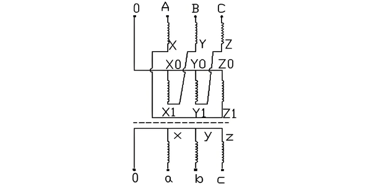
While YNd11-connected transformers can be used, ZNyn11 is preferred (Fig. 1). Key differences:
During single-phase earth faults, selecting appropriate earthing impedance limits phase short-circuit currents to within the main transformer's rated phase current.
2. Zero-Sequence Impedance Analysis of ZN-Connected Earthing Transformers
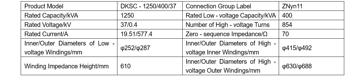
The main technical parameters of the earthing transformer analysis model are shown in Table 1, with the allowable deviation of zero-sequence impedance required to be within ±7.5%.
2.1 Zero-Sequence Impedance Calculation via Traditional Empirical Formula
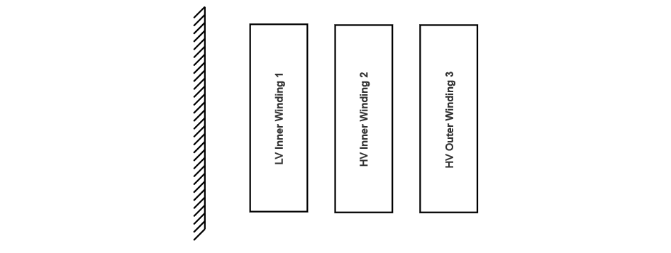
As shown in Figure 2 (earthing transformer winding arrangement), zero-sequence impedance is defined as the ratio of the voltage drop in one phase to the fault current when the fault current flows through all three phases simultaneously. For calculation, X0 follows the impedance principle of ordinary double-winding power transformers (Equation 1).

In the formula, W represents the number of winding turns. For a winding with ZN connection, W is the number of turns of the half - winding; ∑aR denotes the equivalent leakage flux area. For a winding with ZN connection, it is the equivalent leakage flux area of the two half - windings; ρ is the Rogowski coefficient; H is the reactance height of the winding.
Substituting the data in Table 1 into Equation (1), the calculated zero-sequence impedance is 70.6 Ω.
2.2 Zero-Sequence Impedance Analysis via Electromagnetic Software
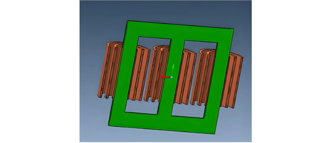
The Magnet electromagnetic software from Infolytica was employed for magnetic field analysis. A 3D simplified model was established based on the product's structural characteristics, as shown in Figure 3. The software utilizes a T-Ω potential group solving algorithm with laminated elements using 1st to 3rd order interpolation polynomials.
Finite element analysis (FEA) is a numerical calculation method rooted in the variational principle and meshing interpolation. It first transforms the boundary value problem into a corresponding variational problem (i.e., an extremum problem of a functional) using the variational principle, then discretizes the variational problem into an extremum problem of a common multivariate function through meshing interpolation, ultimately reducing it to a set of multivariate algebraic equations for solving the numerical solution.During the analysis, the mesh divisions were set as follows: air at 80, iron core at 30, and windings at 15. The product's meshing diagram is detailed in Figure 4.

In finite element algorithms, polynomial order correlates with the accuracy of field - domain shape functions – higher orders better characterize field properties. For this model, a 2nd - order polynomial was adopted, with a maximum of 20 iterations, a 0.5% iteration error, and a 0.01% conjugate gradient error.
To test the zero - sequence impedance of the earthing transformer via the field - circuit coupling method: apply the high - voltage rated current (27.59 A peak for software) at the neutral point, keep the low - voltage side open - circuited, and measure the voltage.
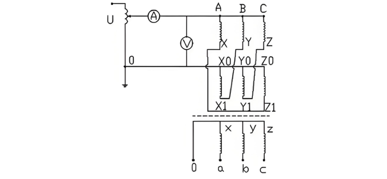
2.3 Zero-Sequence Impedance Measurement
Zero-sequence impedance is measured between the line terminals and neutral terminal of the earthing transformer at rated frequency (as shown in Figure 5), expressed in ohms per phase. Its value is calculated as 3U/I (where U is the test voltage and I is the test current). During the measurement, a rated current of 19.5 A is applied to the line terminals, and the voltage between the line terminals and neutral point is measured as 443.3 V. The calculated zero-sequence impedance is 68.2 Ω.
2.4 Comparative Analysis of Calculated, Simulated and Measured Values
The main performance parameters are compared in Table 2. The results show that both the calculated and simulated zero-sequence impedances of the earthing transformer are close to the measured value, with deviations of 3.5% and 0.88% respectively. The simulation results from the electromagnetic software are closer to the measured values. The magnetic field analysis results help to clearly understand the magnetic field distribution characteristics of the product under this working condition, which can be used to optimize the electromagnetic design and structural design of the product based on the magnetic field distribution characteristics.

The magnetic field simulation results obtained by electromagnetic software are more closely aligned with the measured values. With the help of magnetic field analysis results, the characteristics of the product's magnetic field distribution under this working condition can be more clearly understood, and thus targeted electromagnetic design and structural design of the product can be carried out.
3.Conclusion
Zero-sequence impedance is a key parameter of earthing transformers, with strict deviation requirements from users. When calculating with traditional empirical formulas in engineering, correcting empirical coefficients is needed, which relies heavily on designers' experience and hardly ensures accuracy.
To improve accuracy, this paper uses simulation software for magnetic field analysis, compares with empirical formula results, and verifies through tests. The simulation results are accurate and can meet engineering needs.


