I’m Oliver, an 8 - year current transformer testing pro. Today, let’s break down new and old polarity test methods for GIS current transformers—how they work and their pros/cons.
1.Testing Methods
1.1New Method
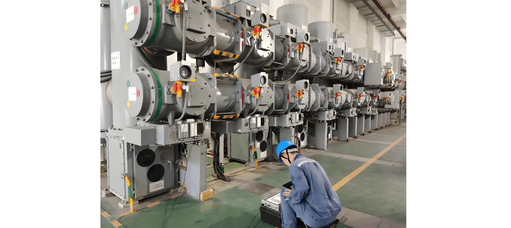
Pre - test ops: Open FDS21/FDS22 fast disconnectors + DS23 disconnector. Close CB21 breaker, then ES21/ES22 grounding disconnectors. Disconnect ES21’s SF6 - shell ground.
Wiring: Connect battery between ES21’s moving contact (negative grounded) + ground electrode. This lets current flow L1→L2 in TA’s primary coil. Wire K1 (CT secondary) to DC milliammeter +ve, K2 to - ve.
Test: Use DC method—apply DC to primary, check milliammeter deflection. Use ≤100mA range (100μA best for clear deflection). Briefly connect/disconnect ES21’s moving contact + K - battery +ve. Positive deflection (battery on) + negative (battery off) means L1 (CT) and K1 (secondary) are same polarity. Note CT primary coil positions; draw results.
1.2 Old Method
Pre - test ops: Close FDS21/FDS22 disconnector, matching disconnector. Open ES21/ES22 grounding disconnectors. Close CB21 breaker.
Wiring: Connect battery +ve to 110kV inlet bushing (Ⅰ/Ⅱ), - ve to GIS outlet bushing. Briefly connect/disconnect. Positive deflection (on) + negative (off) means L1/K1 are same polarity. Note CT positions; draw results.
2 Method Comparison
New: Simple wiring/ops, low energy loss, works with small batteries. Milliammeter deflects sharply—high sensitivity, accurate.
Old: Complex steps, long wires—troublesome on - site. High - altitude risks (battery wiring on bushings). More series components → high impedance → unstable results. Often needs big batteries (rare on - site), risking wrong calls.
3. Safety Must - Dos
Follow strict sequence: Keep CB21 open → open FDS21/FDS22 (line) + DS23 (bus) → close ES21/ES22 (grounding). Critical for live lines/buses—avoids “live + ground disconnector” accidents.
4. Wrap - Up
The new method solves on - site polarity testing pain points, ensures relay protection works, and stabilizes grids. After 8 years in testing, I swear: choosing the right method balances safety + efficiency.

 Login