By Felix, 15 Years in the Electrical Industry
Hi everyone, I'm Felix, and I've been working in the electrical industry for 15 years.
From early involvement in traditional substation commissioning and maintenance to now managing electrical system operations for multiple photovoltaic and wind power projects, one of the most frequently encountered devices I deal with is the Electromagnetic Voltage Transformer (PT).
The other day, a shift operator at a new energy plant asked me:
“We have an electromagnetic voltage transformer that keeps overheating, making strange noises, and sometimes even causing protection malfunctions. What’s going on?”
This is a very common issue, especially in new energy plants. As a key measurement and protection component, once a PT fails, it can cause anything from inaccurate metering to full tripping or even equipment damage.
Today, I want to talk about:
What are the common faults of electromagnetic voltage transformers? Why do they happen? And how do we troubleshoot them?
No complex terminology — just real-life situations I’ve encountered over the years. Let's take a look at what often goes wrong with this "old friend."
1. What Is an Electromagnetic Voltage Transformer?
Let’s start with a quick overview of its basic function.
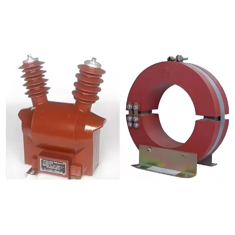
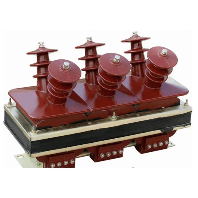
An electromagnetic voltage transformer, also known as a VT or PT, is essentially a step-down transformer that converts high voltage into a standard low voltage (usually 100V or 110V), which is used by measuring instruments and relay protection systems.
Its structure is relatively simple: the primary winding has many turns and thin wire, connected to the high-voltage side; the secondary winding has fewer turns and thicker wire, connected to the control circuit.
However, due to this structural characteristic, it is easily affected by operating conditions, load changes, and resonance phenomena.
2. Common Faults and Root Cause Analysis
Based on my 15 years of field experience, the most common types of faults include:
Fault 1: Abnormal Heating or Even Smoke/Burning
This is one of the most dangerous issues — it can lead to insulation degradation or even fire.

Possible Causes:
Secondary short circuit or overload (e.g., multiple protection devices connected in parallel without checking capacity);
Core saturation (especially during ferroresonance);
Insulation aging or moisture ingress;
Loose terminals causing high contact resistance and localized heating.
Real Case:
Once, I found a PT overheating badly at a PV step-up station — infrared thermography showed temperatures over 120°C. Upon disassembly, we found the secondary winding insulation had burned through. The cause was an open circuit condition caused by a disconnected secondary breaker while still connected to a high-impedance meter.
Tips:
Never allow the PT secondary to run open-circuited — although not as dangerous as CTs, it can still cause voltage distortion and measurement errors;
Use infrared thermography regularly to check terminal and enclosure temperatures;
If abnormal heating is detected, shut down immediately for inspection.
Fault 2: Ferroresonance Causing Voltage Fluctuations
This is one of the most overlooked yet dangerous problems in new energy plants.
Symptoms:
Unbalanced three-phase voltage;
Voltage fluctuating up and down with buzzing noise;
Protection misoperations or false trips;
Sometimes even false ground signals appear.
Root Cause:
In ungrounded or arc suppression coil grounded systems, when line-to-ground capacitance combines with PT excitation inductance under certain conditions, ferroresonance can occur;
It often gets triggered during breaker switching, sudden loss of voltage, or single-phase grounding.
Real Case:
At a wind farm, every time the main transformer was energized, the PT emitted a humming noise, and bus voltage fluctuated wildly, even triggering the standby auto-switch incorrectly. After investigation, it turned out to be caused by ferroresonance. Installing a damping resistor in the open delta solved the problem.
Prevention Suggestions:
Install anti-resonance devices (such as open-delta resistors or microprocessor-based suppressors);
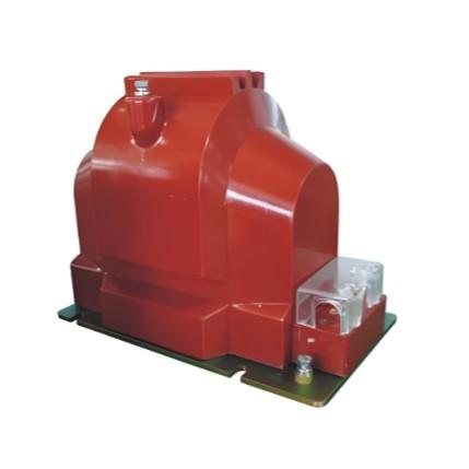
Use anti-resonant type PTs (like JDZXW series);
Optimize operation mode to avoid long-term non-full-phase operation;
During outage maintenance, perform magnetizing curve tests to assess core saturation tendency.
These issues often affect metering and protection logic, and are sometimes mistaken for other device failures.
Possible Causes:
Primary fuse blown (often after lightning strikes or overvoltage events);
Secondary fuse blown or air switch tripped;
Incorrect polarity or ratio setting;
Inter-turn short circuits in internal windings;
Oxidized or loose terminal connections.
Real Case:
In one PV station, SCADA showed abnormally low bus voltage. On-site inspection revealed that the PT primary fuse had blown. Replacing it restored normal operation. Further analysis showed it was caused by a voltage surge from nearby lightning.
Troubleshooting Steps:
Check fuses and breakers first;
Measure primary and secondary voltages for consistency;
Verify wiring and polarity;
Perform ratio test and insulation resistance test if necessary.
Fault 4: Internal Discharge or Insulation Breakdown
This usually occurs in humid or heavily polluted environments, especially in coastal or high-altitude areas.
Symptoms:
Smell of burning or visible discharge marks on housing;
Crackling sounds during operation;
Reduced insulation resistance;
In severe cases, explosion or tripping occurs.
Possible Causes:
Moisture ingress causing insulation deterioration;
Surface dirt or dust buildup reducing creepage distance;
Long-term overloading or harmonic effects;
Manufacturing defects or transport damage.
Real Case:
A PT installed near the coast repeatedly tripped during the rainy season. Inspection revealed clear signs of internal discharge — the root cause was poor sealing allowing moisture to enter.

Countermeasures:
Increase protection rating (IP54 or higher);
Install dehumidifiers or space heaters;
Regular cleaning and drying;
Conduct insulation and partial discharge tests before commissioning.
Fault 5: Human Error or Wiring Mistakes
Human error remains a major cause of many incidents.
Common Mistakes Include:
Switching isolators under secondary load;
Reversed polarity causing incorrect metering or protection misjudgment;
Accidental removal of grounding wires leading to floating potentials;
Performing live work without proper safety measures.
Real Case:
A new technician replaced a PT secondary fuse without disconnecting the power, causing a short circuit — the fuse holder burned out and nearly caused injury.
Key Takeaways:
Strengthen training and standardize procedures;
Clearly label wiring to prevent mistakes;
Enforce lockout/tagout procedures to eliminate live work;
Ensure one-point grounding of all PT secondary circuits.
3. My Suggestions and Field Experience Summary
As a 15-year veteran in the electrical field, I always say:
“Though small, the electromagnetic voltage transformer plays a critical role in measurement, metering, and protection.”
It may not be as noticeable as a circuit breaker or as large as a transformer, but once it fails, it can trigger a chain reaction.
So here are my recommendations:
Regular inspections — listen for unusual sounds, smell for burning, and measure temperature;
Check fuses, breakers, and grounding integrity;
Record operational data and compare with historical trends;
Increase inspection frequency before and after thunderstorm seasons.
For Fault Diagnosis:
Prioritize checks on secondary circuits and fuses;
Use multimeters to verify voltage levels;
Conduct insulation resistance, ratio, and magnetizing characteristic tests when needed;
Take immediate action to suppress resonance if suspected.
For Equipment Selection:
Consider environmental factors (humidity, altitude, salt fog);
Prefer anti-resonant PTs;
Choose appropriate rated capacity to avoid long-term overloading;
Leave room for redundancy to support future expansion.
4. Final Thoughts
Although structurally simple, electromagnetic voltage transformers play a vital role in new energy power plants.
They act like the "eyes" of the power system, telling us exactly how "high" the voltage is.
After 15 years in the field, I firmly believe:
“Details determine success or failure. Safety comes above everything.”
If you're dealing with tricky PT issues on site, feel free to reach out — I'm happy to share more hands-on experiences and troubleshooting methods.
May every PT operate stably, keeping our grid safe and intelligent!
— Felix