Pagkatapos sa proyekto sa pag-renovate sa rural nga grid, ang rural nga distribusyon network nagsilbi og dako nga kaayohan. Sundanon, tungod sa mga limitasyon sama sa terreno, kapaligiran, ug sukol sa investimento, ang layout wala pa optimal. Taliwason, ang radius sa power supply sa pipila ka 10 kV transmission lines gisobrahan sa makatarungan nga rango. Tungod sa mga pagbag-o sa panahon ug adlaw ug gabii, may mga significante nga voltage fluctuations, resulta mao ang mga problema sama sa sub-standard nga kalidad sa power ug relatively mataas nga line losses, nga nagpapakabati sa mga buhi ug produksyon sa mga mag-uuma. Dili kini, ang paper na siya midisenyo og bag-ong tipo nga voltage regulation device: ang feeder automatic voltage regulator.
1 Prinsipyo sa Pagtrabaho sa Voltage Regulator
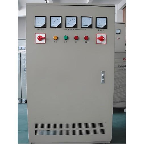
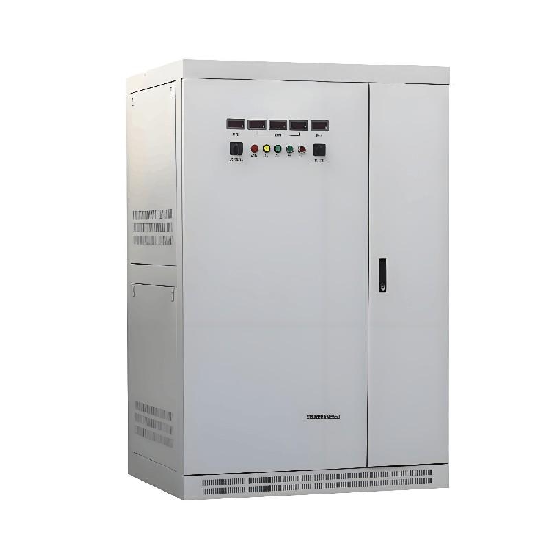
Ang automatic voltage regulator usa ka device nga awtomatikong sumala sa mga pagbag-o sa input voltage aron masiguro ang stable nga output voltage. Kini mahimong gamiton sa maluwas sa 6 kV, 10 kV, ug 35 kV power supply systems, ug mahimo nia ang automatic adjustment sa input voltage sa 20% range. Ang pag-install sa device sa 1/2 o 2/3 sa distansya gikan sa start sa line makapahimulos sa kalidad sa voltage sa line.
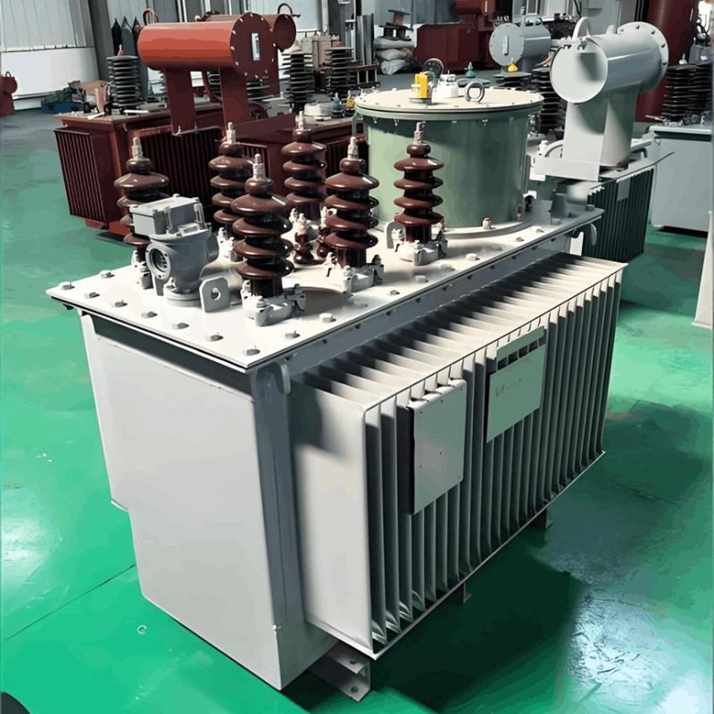
Sa mga substation diin ang main transformer wala mogamit og on-load voltage regulation capability, ang automatic voltage regulator usab mahimo molagda sa outgoing line side sa substation's main transformer aron makamit ang on-load voltage regulation. May daghang taps sa secondary side sa transformer. Tungod sa paggamit sa single-chip microcomputer aron kontrolon ang on-off sa thyristors, ibutang ang iba't ibang lebel sa voltage regulation, resulta makamit ang layo sa feeder voltage regulation.
2 Paghimo sa Tap-changing Action Voltage sa Voltage Regulator
Ang feeder voltage regulator mahimong i-adjust ang mga taps batas sa iba't ibang load conditions ug pagbag-o sa transformation ratio batas sa line voltage aron makamit ang voltage regulation. Adunay 7 taps ug 30% voltage regulation range, hinumdumi kini maayo sa pagsilbi sa rural voltage regulation requirements.
2.1 Prinsipyo sa Paghimo sa Tap-changing Voltage sa Voltage Regulator
Tungod sa mga pagbag-o sa load, ang voltage sa end sa line mahimong mag-usab. Para sa iba't ibang voltage drops, kinahanglan i-adjust ang tap settings sa voltage regulator. Figure 1 nagpakita og typical nga rural transmission power grid. Ania, ang haba sa line gitakda isip L km, ug ang power sa end sa line gitakda isip S = P + jQ MVA.

Mga requirement para sa gear shifting: Siguraduhon nga ang voltage sa end sa line mag-usab sa 7% range; kasagaran, wala gigawasan ang gear skipping; ang numero sa gear shifts dapat mahimong labi ka gamay.
I-assume ang transformation ratio is K, ang voltage sa start sa line is U0, ang voltage sa end sa line is U1, ang input voltage sa voltage regulator is Uin, ug ang output voltage is Uout, uban ang Uout=KUin.
Sumala sa modelo, ang sumala nga equation nagpahimulos:U1=Uout−ΔU1.
Diin Δ U1 ang voltage drop gikan sa installation point sa voltage regulator hangtod sa end sa line, ug x ang distansya gikan sa installation point sa voltage regulator hangtod sa start sa line. Sumala:

(U0 - Uin) ang voltage drop gikan sa start sa line hangtod sa installation point.α = U0/Uout ang line voltage level ratio bago ug human sa installation point sa voltage regulator. Hain (L-x)/x=K1, ug substituting it in, kita ang:

Dito, ang voltage U1 sa end sa line kinahanglan mosatisfy sa constraint condition 9.7 < U1 < 10.7. Substituting it into the above formula, kita ang rango sa Uin under the condition that K known can be obtained. Obvious, tungod sa existence sa U0/Uout, kinahanglan solbahan ang quadratic equation of one variable, ug adunay problem sa spurious roots. Ang paper simplifies this equation.
Para sa analysis sa α=U0/Uout, Uout ug U1 adunay parehas nga increasing or decreasing trend. U0 usa ka constant, so α=U0/Uout, Uout inversely proportional to U1. Usab mahimong gi-analyze nga when U1 = 9.3, α≈1; and when U1=10.7, α slightly less than 1. Therefore, ang constraint equation makapahimulos as:

That is:

2.2 Setting Example
As can be seen from Formula (5), in fact, the setting of the gear-shifting action only relates to the input voltage Uin of the voltage regulator and the ratio Kt of the distance from the voltage regulator installation point to the line length. There is no need to measure the actual load at the end of the line, which greatly simplifies the difficulty of actual engineering.
Take a certain actual transmission line as an example. Still use the model shown in Figure 1. The length of the transmission line is 20 km. The voltage regulator is usually installed in the middle of the line. Here, the distance from the start of the line is taken as x = 9, km, and Kt = 11/9. Substitute into Formula (5), and we can get:

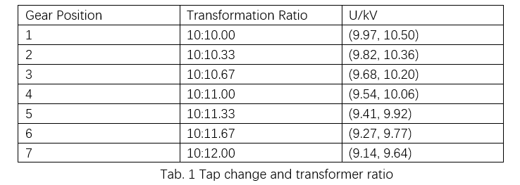
For a certain gear position, the input voltage range that satisfies the quality requirements of the electric energy at the end has upper and lower limits, which are the operating voltages (shift voltages) for that gear. Each gear has its corresponding operating voltage, and this relationship can be more intuitively seen on the number axis.

Among them, Gear 1 is left unused because under normal conditions, the input voltage will not exceed the upper limit of this gear. Gear 1 can be used as a special operating condition, such as fault-tolerant operation during a single-phase ground short circuit. The following describes the switching conditions when the gear reaches the action voltage:

It should be noted that when down-shifting from gear 4, it directly shifts down to gear 2. This is because the lower action limits of gear 3 and gear 4 are relatively close. If the voltage changes greatly, after shifting down from gear 4 to gear 3, it may be necessary to immediately shift down to gear 2, which increases the number of actions. Therefore, to reduce the number of actions, cross-gear shifting is allowed.
3 Design of the Gear-shifting Controller
Currently, the commonly adopted gear-shifting method is to use a motor to drive the movement of the gear switch blade. However, how to ensure the rapid and accurate rotation of the motor has always been a problem. To achieve a better control effect, this paper adopts a thyristor control system.
3.1 Thyristor Control Principle
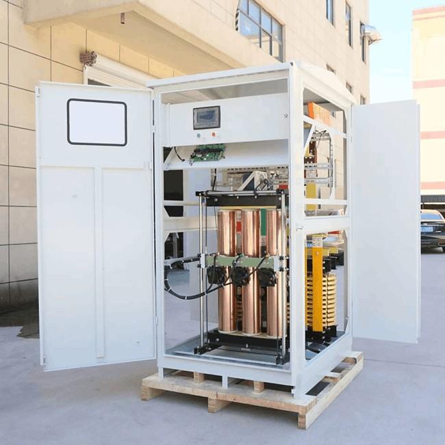
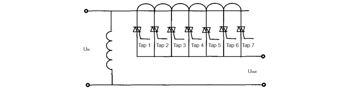
Thyristors can be used to realize the control of high-power circuits with weak currents. The feeder voltage regulator uses 7 pairs of bidirectional thyristors to control the gears, as shown in Figure 2. Each pair of thyristors is connected to different windings of the transformer, thus corresponding to different transformation ratios.
3.2 Design of Single-chip Microcomputer Gear-shifting Controller
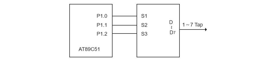
The control of bidirectional thyristors only requires voltage driving from TTL gate circuits and can be directly connected to the output port of the single-chip microcomputer. To save output ports, only 3 ports are used, and an external 3-to-8 decoder is connected to drive the control of 7 gear positions, as shown in Figure 3.
4 Design of the Intelligent Control System
For a voltage regulator with a control chip, having only the automatic voltage regulation function is insufficient, and it also fails to fully utilize the performance of the single-chip microcomputer. A complete control system, as shown in Figure 4, also includes keyboard input, a display circuit, wireless communication, an external clock, external storage, and fault protection.
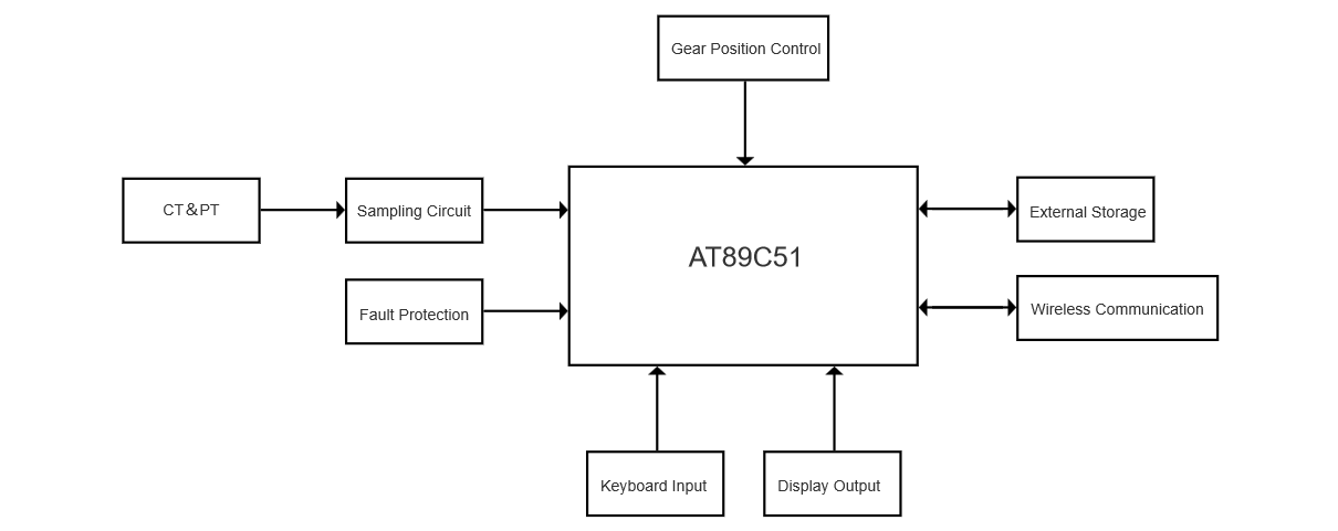
Keyboard input enables program adjustment, wireless communication allows real-time monitoring of the voltage regulator’s operation. The external clock ensures time recording during single-chip microcomputer power failure. External storage safely stores massive system operation data for future research. Fault protection makes the single-chip microcomputer enter a special operation mode under abnormal conditions to meet power transmission tasks, protects it from damage under faults, and cooperates with relay protection devices to safeguard transmission lines.
5 Conclusion
By building a transmission line model and conducting load flow calculations, the setting rules for the voltage regulator gear action voltage are determined. For transformer tap control, traditional mechanical control is replaced with more convenient and faster thyristor control, featuring simple design and good control effect. The feeder automatic voltage regulator has a wide voltage regulation range, effectively ensuring the voltage quality of transmission lines.