Voltage is an important criterion in power quality testing. The quality of voltage determines whether the power system can operate safely and has a significant impact on the stability of the entire power grid system. Currently, voltage regulators are relatively common electrical equipment in power systems, capable of reasonably and scientifically controlling the entire process of high-voltage tests on electrical equipment, thereby continuously improving the feasibility of such tests.
1. Requirements for Using Voltage Regulators in High-Voltage Tests of Electrical Equipment
Under normal circumstances, before initiating a high-voltage test on electrical equipment, a voltage regulator installed at the front end of the transformer must be selected to ensure that its specifications meet the test requirements. This guarantees that the measurement results from the transformer satisfy the standard test criteria—namely, that the output remains stable, continuous, and changes uniformly, thus enabling effective voltage regulation. The use of voltage regulators in high-voltage tests of electrical equipment entails the following requirements:
Ensure stable and high-quality voltage output; for example, the output voltage waveform of the regulator should approximate a sine wave, and the minimum output voltage should be as close to zero as possible.
The voltage regulator must possess high-quality regulation characteristics, with low regulation impedance, simple and safe adjustment methods, to facilitate smooth high-voltage testing of electrical equipment.
Minimize noise generated during operation of the voltage regulator and emphasize energy efficiency and environmental protection during testing.
Ensure that fundamental parameters of the voltage regulator—including output voltage, frequency, number of phases, and fluctuations in output capacity—meet the requirements of high-voltage tests on electrical equipment. Specifically, the accuracy of the voltage regulator is expressed as:
tgδ: ±(1% D + 0.0004)
Cx: ±(1% C + 1 pF)
A smaller error indicates better instrument precision. During verification, the difference between the reading and the standard value must be less than the specified accuracy.
2. Application of Voltage Regulators in High-Voltage Tests of Electrical Equipment
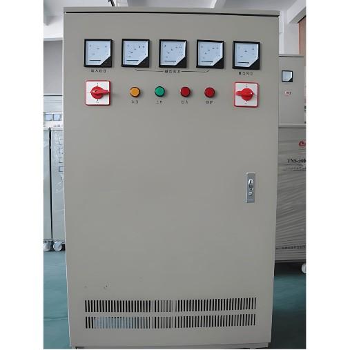
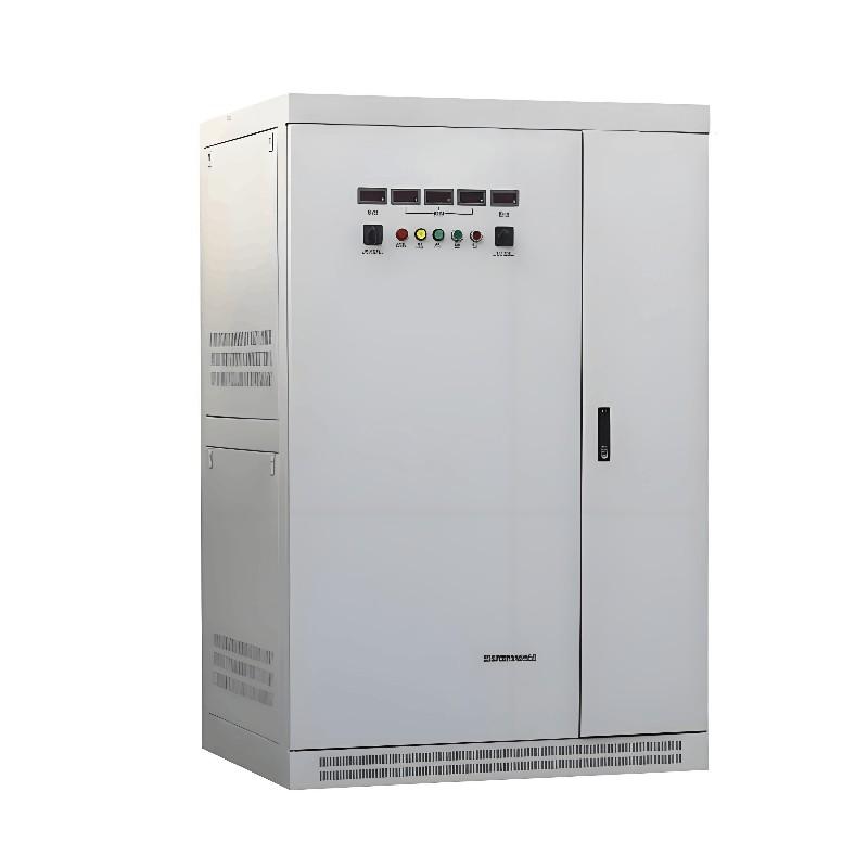
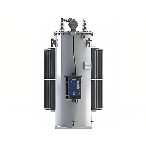
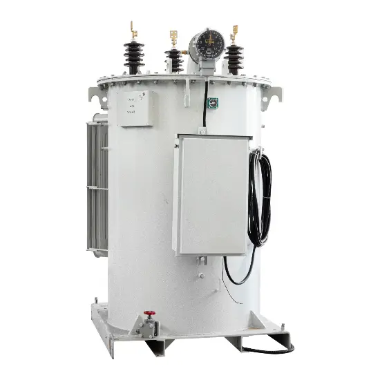
Three types of voltage regulators are commonly used in high-voltage tests of electrical equipment: contact-type regulators, induction regulators, and moving-coil regulators. These three types differ significantly in structure and operating principle, and each has distinct application scenarios and usage characteristics.
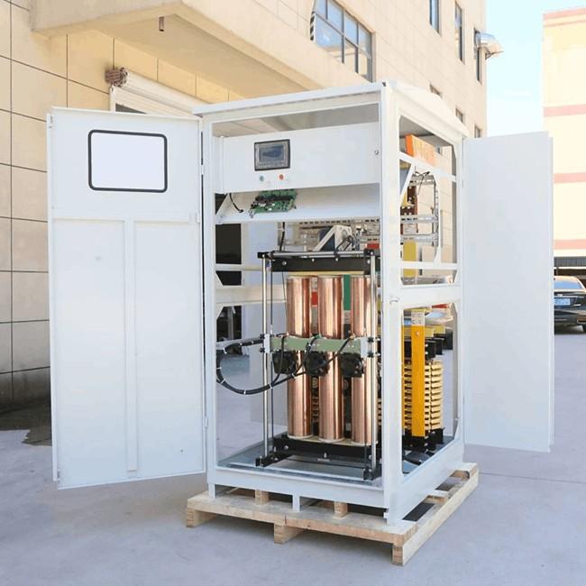
During high-voltage testing, voltage regulators generally assist asynchronous motors and mechanisms in energy conversion and are electrical devices closely related to transformers. In high-voltage tests, the motor must comply with the voltage regulator’s maximum load capacity requirement of 12,000 kW. Additionally, to reduce electromagnetic noise, the mechanical strength of the regulator should be enhanced by using a solid cast-iron structure.
2.1 Use of Moving-Coil Voltage Regulators
The electromagnetic principle and internal structure of moving-coil voltage regulators resemble those of transformers. They achieve effective output voltage regulation by vertically moving a short-circuited winding along the core limb to alter the voltage and impedance distribution between the two windings in the main circuit. Since regulation does not rely on contacts, the output voltage from a moving-coil regulator is relatively smooth and uniform, making it easy and convenient to use for general high-voltage tests on electrical equipment.
Moreover, its large leakage reactance enables it to withstand substantial current surges. However, due to its structural and operational characteristics, the moving-coil regulator exhibits relatively high short-circuit impedance. Therefore, it is unsuitable for high-voltage test projects requiring low source impedance, such as high-voltage pollution (contamination) tests. Compared to induction regulators, the output waveform of moving-coil regulators is more prone to distortion.
Furthermore, after prolonged use, wear and loosening of the transmission components and movable coil may increase noise and vibration, potentially leading to damage. Power flow algorithms can be used to calculate the complex components of voltage loss in power systems. Specifically, this involves leveraging the relationship between node voltages, active power, and the magnitude of node voltages to decompose P-Q equations, reducing the coefficient matrix from 2N×2N to N×N, where N is the number of system nodes.
2.2 Use of Induction Voltage Regulators
The electromagnetic principle and structure of induction voltage regulators are similar to those of wound-rotor stalled asynchronous motors, while their energy conversion mechanism resembles that of transformers. By adjusting the angular displacement of the rotor, they modify the magnitude and phase of the induced electromotive force in the stator or rotor windings, achieving contactless voltage regulation.

Compared to moving-coil regulators, induction regulators offer superior overall technical and economic performance and lower impedance—especially when the output voltage is within the 50%–100% range, where impedance is notably lower. However, due to structural and operational limitations, single-phase induction regulators have high manufacturing costs, particularly for large-capacity units. When the rotor eccentricity of a single-phase unit reaches a certain threshold, noise and vibration issues may arise during operation, limiting its output capacity. Consequently, large-capacity single-phase induction regulators are rarely produced today. Nevertheless, improved versions of induction regulators are effectively used in high-voltage tests with less stringent requirements.
2.3 Use of Contact-Type Voltage Regulators
Contact-type voltage regulators are autotransformers capable of providing continuous voltage output. They produce output voltage waveforms with excellent sinusoidal characteristics, with a lower output limit of 0 V, and exhibit linear, continuous, and smooth regulation characteristics. Additionally, their short-circuit impedance can be minimized, and they feature nearly identical phase angles between input and output voltages and low operational noise, making them ideal for high-voltage tests on electrical equipment. Depending on core configuration, contact-type regulators are classified into column-type and toroidal-type.
Traditionally, small-capacity high-voltage tests predominantly used toroidal contact-type regulators due to their low cost and excellent performance. The most notable drawback of contact-type regulators is their reliance on physical contacts for adjustment, which can generate sparks during operation. Contact capacity is also limited, and their relatively short service life has hindered the development of large-capacity models. However, thanks to continuous efforts by technical personnel, contact-related issues have been largely resolved.
3. Maintenance of Voltage Regulators in High-Voltage Tests of Electrical Equipment
Before performing maintenance on voltage regulators used in high-voltage tests of electrical equipment, personnel must thoroughly understand the internal structure of the regulator to accurately locate faults and improve maintenance efficiency. The basic structure of the voltage regulator is shown in Table 1.
| Internal Composition | Component Parts |
| Cavity | Front body, rear body, internal airtight parts |
| Pilot Valve | Pressure-regulating screw, nozzle baffle, small valve body |
| Main Voltage Regulator | Adjustment rod, front body, conical spring, air guide rod, O-ring, screw, screw sleeve |
3.2 Voltage Regulator Gas Leakage Issues
In high-voltage tests of electrical equipment, gas leakage from voltage regulators is typically caused by insufficient sealing of O-rings and connection joints. It may also result from damage to the sealing metal between the adjusting seat and the adjusting rod. The specific solution involves shutting off the gas circuit, disassembling the main valve end of the voltage regulator, and having technicians carefully inspect to identify the exact location and nature of the fault. Based on practical experience, appropriate improvements are then implemented to resolve gas leakage from the pressure relief port during regulation in high-voltage tests.
During high-voltage testing, a common issue is gas leakage occurring at the zero position during adjustment. This is primarily due to over-tightening the zero-adjustment screw. To mitigate this, the position of the zero-adjustment screw should be properly adjusted to reduce the likelihood of leakage at the zero position.
It should be noted that operators must avoid standing directly in front of the voltage regulator during adjustment to minimize the risk of accidents.
4. Conclusion
In practical applications, when conducting high-voltage tests on electrical equipment, personnel safety must be prioritized. Ensuring the safety of both personnel and equipment is the fundamental prerequisite for performing proper troubleshooting and maintenance on test components. This approach effectively extends equipment service life and reduces the incidence of failures. With the widespread application of voltage regulators in high-voltage testing of electrical equipment, convenience is brought to residents’ daily lives and various aspects of society, thereby promoting harmonious social development.