Application of Bidirectional Automatic Voltage Regulators in Mountain Distribution Networks

1. Overview
Mountain distribution networks are equipped with numerous small hydropower stations, most of which are run-of-river stations without regulation capacity. These stations are connected to the same line as electrical loads, bringing certain negative impacts on power grid operation. The most prominent issue among them is the voltage quality problem. During the wet season, small hydropower stations generate electricity to the grid, and the failure to achieve local power balance leads to elevated line voltage.
During the dry season, due to the long line length, small wire diameter, and low load, the voltage at the end-users of the line is extremely low. As power generation and supply are integrated on the same line, the line power flow direction is variable, resulting in highly unstable voltage. Installing bidirectional feeder automatic voltage regulators in long distribution lines can solve the voltage quality problem. Focusing on the voltage quality issues of mountain distribution lines with small hydropower stations, this paper takes Bibei Line of a certain Power Supply Bureau as an example and proposes a new type of bidirectional automatic voltage regulator solution.
1.1 Basic Information of 10kV Bibei Line
As a typical representative of mountain distribution network lines, the basic information of the 10kV Bibei Line is shown in Table 1 below.
Parameter Name |
Parameter Value |
Parameter Name |
Parameter Value |
Parameter Name |
Parameter Value |
Main Line Model |
LGJ-95 |
Main Line Length |
15.296km |
Total Connected Load of Electricity Consumers |
1250kVA |
Small Hydropower Installed Capacity |
5800kW |
Maximum Voltage |
11.9kV |
Minimum Voltage |
9.09kV |
Statistics on the 2012 voltage qualification rate indicators of 39 distribution transformers in the supply area show that the maximum rate is 99.8%, the minimum is 54.4%, and only 6 distribution transformers meet the standard requirements for voltage qualification rate, accounting for 15.3%. The maximum recorded voltage value is 337V, exceeding the allowable value by 43%. The voltage problem is prominent, with frequent occurrences of electrical appliance damage among users and numerous voltage complaints.
1.2 Analysis of Voltage Anomalies
The main reasons leading to the voltage quality problem of Bibei Line are as follows:
(1) Prominent contradiction between wet and dry seasons. The operation mode of run-of-river hydropower units is closely related to water inflow. Since the installed capacity of small hydropower stations is much larger than the load capacity, a large amount of surplus electrical energy is transmitted to the grid during the wet season. During the dry season, the local power supply load mainly relies on grid supplementation, resulting in significant changes in the operation mode between wet and dry seasons, which seriously affects power quality and makes it difficult for the voltage level in the area to reach the qualified level.
(2) Lack of effective dispatching and monitoring for small hydropower stations. Due to the small single-unit capacity, large quantity, wide distribution, diverse property rights, and significant seasonal impact on operation of small hydropower stations, it is difficult to achieve unified monitoring and control. Therefore, local adjustments for individual transformer areas have an insignificant effect on improving voltage quality.
(3) Difficult operation and regulation of transformers. The line power flow direction changes frequently. During the wet season, power is generated to the grid, and distribution transformers are operated with tap changers adjusted for voltage reduction to ensure that user-end voltage does not burn electrical appliances due to excessive levels. During the dry season, power is absorbed from the grid, and distribution transformers are operated with tap changers adjusted for voltage boosting to ensure that user-end voltage can be normally used without being too low. Therefore, the requirements for step-down and step-up operation of transformers change frequently, making it difficult to perform operation adjustments in coordination with power flow changes.
(4) The main transformer of the upper-level power supply adopts off-load tap changing with a small number of taps and a limited regulation range.
2. Application of Bidirectional Voltage Regulating Transformers
2.1 Selection of Solutions
By studying the operational characteristics of mountain distribution networks with a large number of small hydropower stations and analyzing the applicability of existing voltage regulation methods, this paper selects a bidirectional automatic voltage regulator solution with strong operability and good practicality.
Voltage Regulation Method |
Main Function |
Disadvantages |
Build New Dedicated Lines for Small Hydropower |
Separate Power Generation and Supply |
High investment, long cycle |
Replace Main Line Conductors |
Reduce Line Impedance |
High investment, long cycle, insignificant effect |
Retrofit Main Transformer with On-Load Tap Changer |
Adjust Line Voltage |
Limited regulation capacity for long lines |
Install Capacitors on Distribution Transformers |
Reactive Power Compensation |
Manual switching, not suitable for wet seasons |
Feeder Automatic Voltage Regulator |
Automatically Identify Power Flow Direction |
Connected in series with the line, cannot operate overloaded |
2.2 Principle and Effects of Bidirectional Voltage Regulating Transformers
2.2.1 Working Principle of Bidirectional Feeder Automatic Voltage Regulator
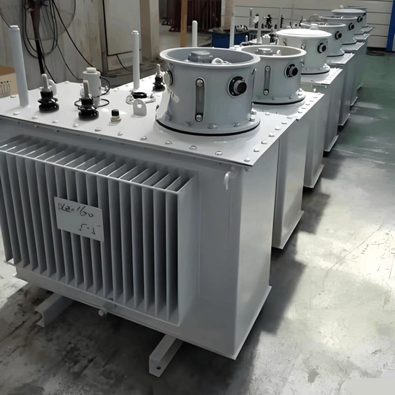
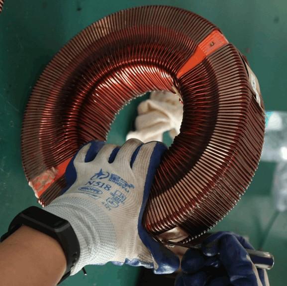
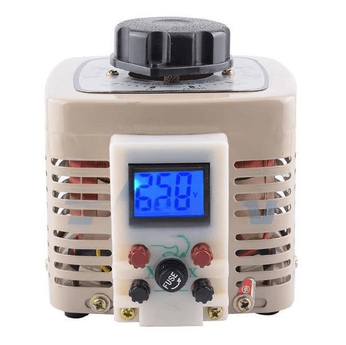
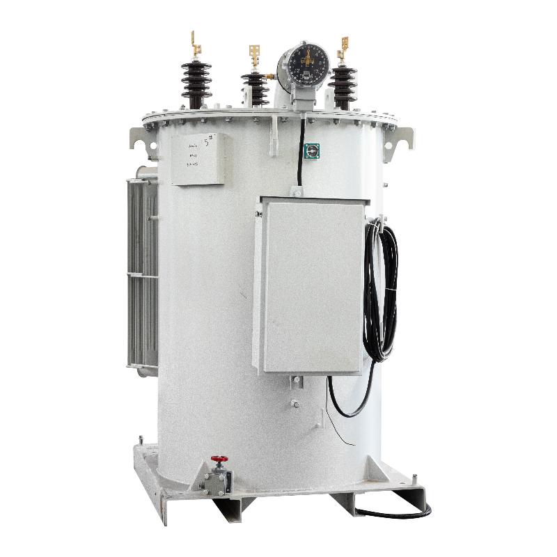
The bidirectional feeder automatic voltage regulator mainly consists of four parts: a three-phase autotransformer voltage regulator, a three-phase on-load tap changer, a controller, and a power flow identification module. The power flow identification module detects the current direction to identify the line power flow direction and sends this signal to the controller. The controller makes a judgment on whether to step up or step down the voltage based on the voltage and current signals, then controls the motor operation inside the on-load tap changer to drive the tap changer to switch taps. This changes the transformer's turns ratio to achieve on-load automatic voltage regulation. The three-phase on-load tap changer adjusts the transformer's turns ratio to change its output voltage.
2.2.2 Theoretical Effect Analysis
Dry Season:The changes in line voltage before and after BSVR installation are shown in Figure 1.

During the dry season, after installing the BSVR bidirectional voltage regulator, the voltages at the end of the main line and on each branch line are increased. This solves the problem of unqualified line voltage and ensures the quality of electricity consumption for users on the line during the dry season.
Wet Season:The voltages at various points of the line before and after BSVR installation during the wet season are shown in Figure 2.

During the wet season, the installation of the BSVR bidirectional voltage regulator improves the voltages at the end of the main line and on each branch line. It not only ensures the normal power transmission from small hydropower stations to the grid but also guarantees the electricity consumption quality of users in the middle and rear sections of the line.
2.3 Application Effects
According to the actual conditions of the line, the bidirectional voltage regulator is installed at Pole 63 of the main line with a capacity of 3000kVA. Considering the actual conditions of both dry and wet seasons comprehensively, the regulator's adjustment range is selected as -15% to +15%.
The voltage quality of this line has been significantly improved. It not only lowers the threshold voltage for small hydropower stations to transmit power to the main grid (so the hydropower stations do not need to raise the voltage excessively) but also boosts the voltage at the starting section of the line via the regulator. This ensures that the hydropower stations can feed power into the grid, while also increasing the voltage qualification rate for customers on the line and guaranteeing the safe and stable operation of the power grid.
3. Conclusion
When the bidirectional automatic voltage regulation device is applied to lines supplied by small hydropower stations, both theoretical calculations and practical applications show that installing a bidirectional feeder automatic voltage regulator can greatly improve voltage quality, comprehensively resolving the voltage regulation conflict between wet and dry seasons.