1.Physical Mechanism: The "Forced Interruption" of Vacuum Arcs
Vacuum Circuit Breakers (VCBs) achieve arc extinction through the extremely rapid dielectric recovery of a high-vacuum medium. When interrupting small inductive currents (such as no-load transformers or motors), the metal vapor plasma may vanish abruptly before the natural current zero. This creates a near-infinite current change rate (di/dtdi/dt), which, according to Faraday’s Law e=L⋅(di/dt), induces an extremely high overvoltage on the inductive load side—known as "Current Chopping Overvoltage."
2. System Hazards: Multiple Restrikes and Steep-Fronted Waves
- Restrike Cycles: If the initial chopping voltage exceeds the dielectric strength of the widening contact gap, it triggers a vicious cycle of "interruption-restrike-re-interruption."
- Insulation Damage: The high-frequency oscillations generate "steep-fronted" waves that are highly destructive to the inter-turn insulation of transformers or motors. The peak magnitude can reach 5 to 8 times the rated voltage, far exceeding the insulation endurance limits of the equipment.
3. Engineering Mitigation Strategies:
- Material Optimization: Implementing CuCr (Copper-Chromium) alloy contacts to stabilize the chopping current between 2A and 5A, mitigating the overvoltage intensity at its source.
- RC Snubbers: Utilizing resistance-capacitance circuits to decrease the transient frequency and absorb surge energy, thereby shielding the equipment's primary insulation.
- Metal Oxide Arresters (MOA): Providing non-linear resistance to effectively clamp the maximum magnitude of the overvoltage within safe limits.
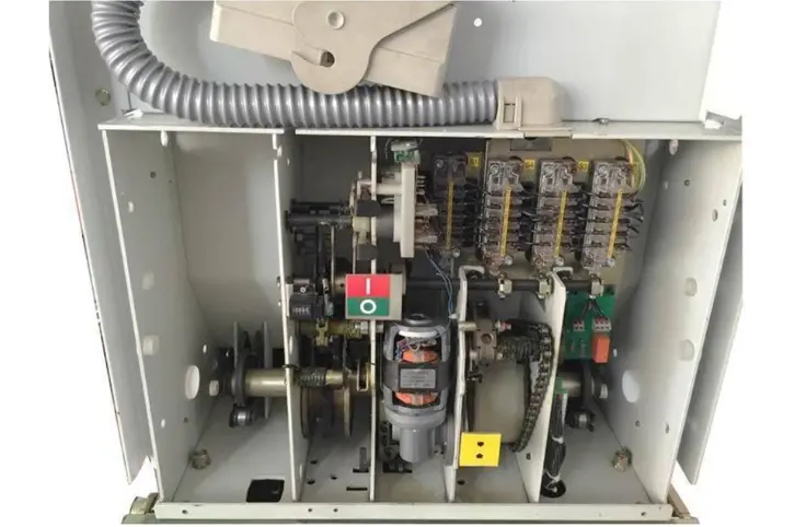
4. Engineering Protection Strategies: Downstream Equipment Protection
For various operating conditions, the following combined solutions are typically adopted in engineering practice:
5. Expert Perspective: Adaptability Suggestions for International Projects
In your overseas power engineering practices, special attention should be paid to the following factors:
- System Frequency Differences: In 60Hz systems, the probability distribution of current chopping overvoltage differs slightly from 50Hz systems. It is essential to re-verify and calculate the RC snubber parameters to ensure effective damping.
- Altitude Correction (Derating): In high-altitude regions, the dielectric strength of air inside the switchgear cabinet decreases. While this does not affect the internal vacuum of the interrupter, it reduces the external flashover voltage of arresters and cable terminations. Therefore, selecting MOAs with higher rated voltages or increased creepage distances is necessary.
- Cable Capacitance Effect: If the cable run between the circuit breaker and the transformer is significant (exceeding 50–100 meters), the distributed capacitance of the long cable can provide a "natural absorption" effect. In such cases, the requirements for RC protection may be simplified or potentially waived after transient analysis.

 Login