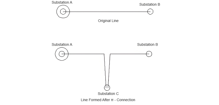
In transmission lines, a "π" connection involves breaking the original line from Substation A to Substation B and inserting Substation C, forming a "π" configuration. After the "π" connection, the original single line is divided into two independent transmission lines. Following the "π" connection, Substations B and C may both be powered by Substation A (in this case, Substation C receives power via a feeder from Substation B's busbar, or possibly from another voltage point within Substation B); alternatively, Substation C may be powered by another substation, forming a "loop network" supply configuration between Substations B and C. As shown in the figure below:
In transmission lines, a "T" connection involves tapping into an existing line from Substation A to Substation B at a certain point without breaking the original line, and connecting a new branch to Substation C. After the "T" connection, the original single transmission line forms a branch, similar to a fork in the road. The "T" connection does not create two independent transmission lines; theoretically, it remains one single transmission line. In this configuration, both Substations B and C are typically powered by Substation A. As shown in the figure below:
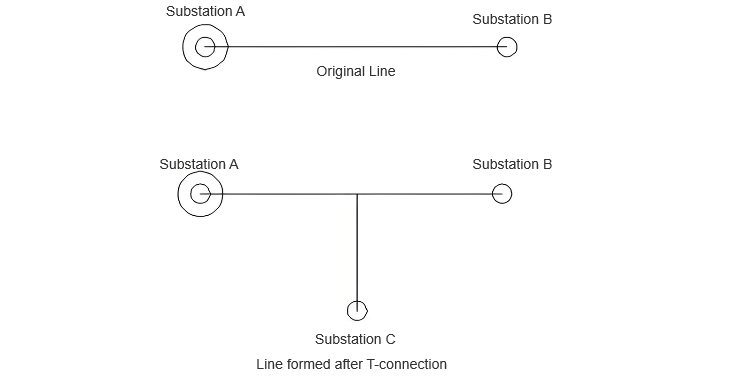
The common point between "T" connection and "π" connection is that both are methods of tapping power to supply a third party.

 Login