3. High-Precision Control Algorithms
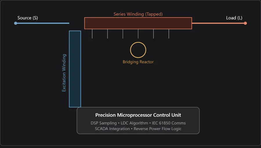
The "Precision" in modern SVRs is a function of the Line Drop Compensation (LDC) and Adaptive Bandwidth settings.
3.1 Line Drop Compensation (LDC)
The SVR does not simply regulate the voltage at its terminals; it regulates the voltage at a "Center of Load" (CoL). The controller calculates the voltage drop across the line using the following phasor relationship:
Vreg=Vload+IL×(Rset+jXset)Vreg=Vload+IL×(Rset+jXset)
Where:
- VregVreg: Voltage at the regulator output.
- ILIL: Real-time load current (measured via CT).
- Rset/XsetRset/Xset: Programmed resistance and reactance representing the feeder's impedance to the CoL.
3.2 Precision Parameters
- Bandwidth (Voltage Window): Typically set between 1.0V and 3.0V (on a 120V base). A tighter bandwidth ensures high precision but increases tap changer operations.
- Time Delay: A programmable delay (typically 30–60s) used to ignore transient voltage dips (e.g., motor starts), preventing "hunting" and mechanical wear.
- Step Voltage: Fixed at 0.625% per step. In a 32-step system, this provides a total range of ±10% (32×0.625%=20%32×0.625%=20%).
4. Advanced Operational Challenges
4.1 Reverse Power Flow (The "Solar Peak" Problem)
With high PV penetration, power often flows from the end of the feeder back to the substation.
- Challenge: Standard LDC logic assumes power flows towards the load. Reverse flow would cause the regulator to lower the voltage incorrectly.
- Precision Solution: High-precision controllers detect the phase angle between voltage and current. When reverse flow is detected, the unit switches to a "Neutral Idle," "Bi-directional," or "Co-generation" mode, ensuring voltage does not exceed upper limits at the PV injection point.
4.2 Harmonic Distortion and Sampling
Non-linear loads introduce harmonics (3rd, 5th, 7th). High-precision units use True RMS sampling at rates exceeding 64 samples per cycle. This ensures that the regulator responds to the heating effect of the voltage rather than just the peak, preventing errors in high-distortion environments.
5. Comparative Analysis: Precision vs. Traditional Units
| Metric |
Traditional SVR |
High-Precision SVR (Modern) |
| Step Resolution |
1.25% (16 steps) |
0.625% (32 steps) |
| Control Logic |
Analog/Electromechanical |
DSP/FPGA Microprocessor |
| Arc Quenching |
In-Oil Arcing |
Vacuum Interruption |
| Data Logging |
None |
Event Recording / Waveform Capture |
| Communication |
None / DNP3 |
DNP3 / IEC 61850 / GOOSE |
| Accuracy Class |
1.0% |
0.2% - 0.5% |
6. Maintenance and Asset Management
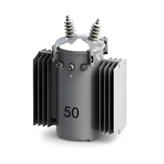
High-precision SVRs are designed for a 30-40 year service life. Key maintenance indicators include:
- Tap Count Monitoring: Used to predict mechanical fatigue.
- Dissolved Gas Analysis (DGA): Monitoring for thermal faults in the autotransformer core.
- Contact Wear Calculation: Advanced controllers estimate contact erosion based on the current interrupted during each step.
7. Conclusion
The high-precision Step Voltage Regulator is a cornerstone of the Grid Modernization initiative. By combining robust electromagnetic design with high-speed digital control, it enables utilities to squeeze more capacity out of existing feeders while maintaining the tight voltage tolerances required by high-tech industries and residential DERs.
Expert Note: When specifying an SVR for a network with high EV charging or solar volatility, always prioritize units with "Selectable Reverse Power Flow" logic and "Integrated Communications" to allow for coordinated Volt-VAR Optimization (VVO).

 Login