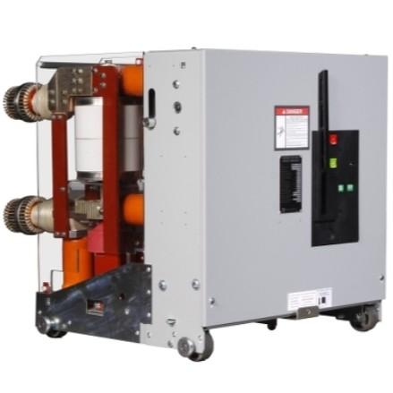
1 Ring Network Power Supply and Ring Main Units
With the advancement of urbanization, the demand for higher reliability in power distribution continues to grow, and an increasing number of users require two or more power supply sources. The traditional "radial power supply" method faces challenges such as difficulties in cable installation, complicated fault detection, and inflexibility in grid upgrades and expansions. In contrast, "ring network power supply" enables dual or multiple power sources for critical loads, simplifies distribution lines, facilitates cable laying, reduces the number of switchgear, lowers failure rates, and makes fault location easier.
1.1 Ring Network Power Supply
Ring network power supply refers to a configuration where two or more outgoing lines from different substations or different busbars of the same substation are interconnected to form a closed loop for power distribution. Its main advantage is that each distribution branch can receive power from either side of the ring. If one side fails, power can still be supplied from the other side. Although operating in a single-loop mode, each branch effectively achieves a dual-power-source reliability level, significantly enhancing system reliability. In China, urban ring network power systems follow the "N−1 security criterion," meaning that if any one of N loads fails, the remaining N−1 loads can still be safely powered without interruption or load shedding.
1.2 Ring Network Connection Configurations
(1) Basic Ring Connection: Single power source with the cables forming a ring, ensuring continued power supply to other loads if one cable section fails (see Fig. 1).
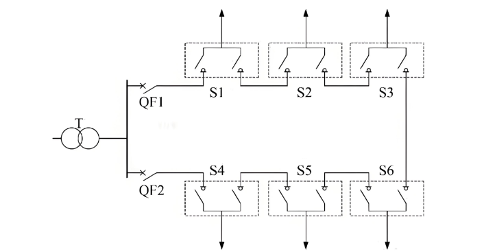
(2) Ring Connection from Different Busbars: Two power sources, typically operated in open-loop mode, offering high reliability and flexible operation (see Fig. 2).
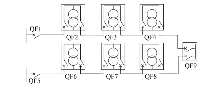
(3) Single Ring Configuration: Power sources derived from different substations or busbars; maintenance on any cable section does not interrupt power to any load (see Fig. 3).
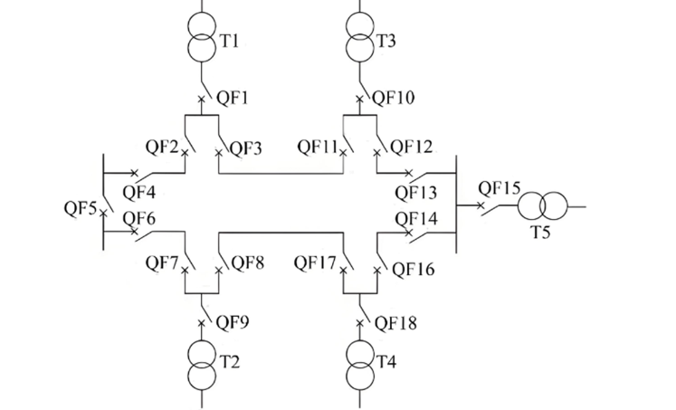
(4) Double Ring Configuration: Each load is supplied from two independent ring networks, providing extremely high reliability (see Fig. 4).
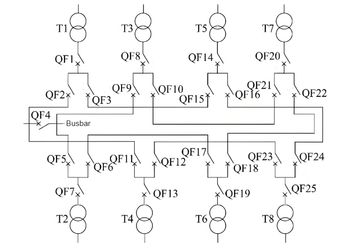
(5) Dual-Supply Double "T" Connection: Two cable lines connected to different busbar sections, allowing each load to receive power from both lines. This configuration ensures near-continuous power supply for dual-source users and is especially suitable for critical applications (see Fig. 5).
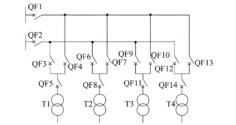
1.3 Ring Main Units and Their Characteristics
A ring main unit (RMU) is a switchgear used in ring network power systems, typically incorporating load break switches, circuit breakers, fuse-switch combinations, bus couplers, metering devices, voltage transformers, or any combination thereof. RMUs are compact, space-saving, cost-effective, easy to install, and quick to commission, meeting the demand for "equipment miniaturization." They are widely used in residential communities, public buildings, small and medium enterprise substations, secondary switching stations, pad-mounted substations, and cable distribution boxes.
1.4 Types of Ring Main Units
Air-Insulated RMUs: Use air as the insulating medium; these units are large in size, require more space, and are susceptible to environmental conditions.
SF₆ RMUs: Utilize sulfur hexafluoride (SF₆) gas as both insulating and arc-quenching medium. The main switch is sealed in a metal enclosure filled with SF₆, while the operating mechanism is located outside. The sealed design minimizes environmental impact and allows for a significantly smaller footprint compared to air-insulated units. SF₆ RMUs are currently the most widely used type.
Solid-Insulated RMUs: Employ solid insulation materials (e.g., epoxy resin) to encapsulate and cast the switches and all live parts. This design reduces phase-to-phase and phase-to-ground insulation distances, resulting in compact dimensions comparable to SF₆ RMUs. Additionally, they eliminate SF₆ emissions and can achieve maintenance-free operation.
2 Limitations of SF₆ Ring Main Units
SF₆ is a major contributor to the greenhouse effect. Despite its excellent electrical properties—such as high dielectric strength, effective arc quenching, good thermal stability, and strong electronegativity—and its insensitivity to humidity, pollution, and high altitudes, making it ideal for compact electrical equipment, SF₆ is recognized as a potent greenhouse gas. Approximately 80% of global SF₆ production is used in the power industry. Both the Intergovernmental Panel on Climate Change (IPCC) and the U.S. Environmental Protection Agency (EPA) classify SF₆ as one of the most harmful greenhouse gases. The EU F-Gas Regulation (2006) prohibits the use of SF₆ in most applications, except where no viable alternatives exist for electrical switchgear.
Moreover, SF₆ RMUs involve high usage complexity and significant investment, requiring various auxiliary equipment:
SF₆ leak detection systems for monitoring gas leakage, concentration, oxygen levels, and moisture content.
SF₆ recovery equipment: During arc interruption, by-products such as SF₄ are generated; thus, at end-of-life, not only must residual SF₆ be recovered, but toxic by-products must also be specially treated.
SF₆ purification systems to clean and reuse the gas.
Ventilation systems in substations.
When using SF₆ RMUs, the following measures must be observed:
Minimize SF₆ leakage. Although SF₆ RMUs use overpressure-sealed enclosures, gas leakage is inevitable. Reduced gas pressure lowers switching reliability, directly endangering personnel safety and shortening equipment life.
Personnel must perform forced ventilation and wear specialized protective gear before entering substations with SF₆ equipment.
Operations are complex, requiring thorough and repeated training for relevant personnel.
3 Features and Applications of Solid-Insulated Ring Main Units
The potential environmental hazards associated with SF₆ ring main units (RMUs) have limited their further development, making the search for SF₆ alternatives a key research focus worldwide. Solid-insulated RMUs were first developed and introduced by Eaton Corporation of the United States at the end of the 1990s. These units produce no harmful gases during operation, have no environmental impact, offer higher reliability, and achieve true maintenance-free operation.
A solid-insulated RMU integrates vacuum interrupters, disconnect switches, grounding switches, main conductors, branch busbars, or combinations thereof, encapsulated within epoxy resin or other solid insulation materials. These components are sealed in fully insulated and fully sealed functional modules that can be recombined or expanded. Conductive or semiconductive shielding layers are applied to the outer surfaces of modules accessible to personnel, ensuring reliable grounding.
3.1 Features of Solid-Insulated Ring Main Units
(1) Environmentally Friendly Design. These units do not use SF₆ as insulation or arc-quenching medium. Instead, they employ vacuum interrupters for switching and environmentally benign, recyclable materials for primary insulation. By minimizing the number of components, they ensure low energy consumption and reduced failure rates during operation.
(2) Truly Maintenance-Free. Solid-insulated RMUs eliminate the need for SF₆ pressure vessels. Internal insulation and arc interruption rely on vacuum technology, while external insulation uses solid materials such as insulating housings. Through potting technology, the vacuum interrupter, main conductive path, and insulation supports are integrated into a single unit sealed within a metal enclosure, making performance immune to external environmental factors. The fully insulated and sealed structure eliminates the need for SF₆ leak detection, gas refilling, and waste disposal, enabling truly maintenance-free operation.
(3) High Cost-Effectiveness. Although the initial investment for solid-insulated RMUs is slightly higher than that of SF₆ RMUs, the total lifecycle cost is significantly lower, as shown in Table 1. Users are increasingly considering comprehensive factors such as safety risks, power quality, cost control, and sustainability—not just initial purchase price—but also total cost of ownership. The cumulative costs of maintenance, gas refilling, leak management, and end-of-life recovery for SF₆ RMUs can approach their initial purchase cost, whereas solid-insulated RMUs require no additional costs after installation. Thus, from a long-term perspective, solid-insulated RMUs offer superior economic benefits.
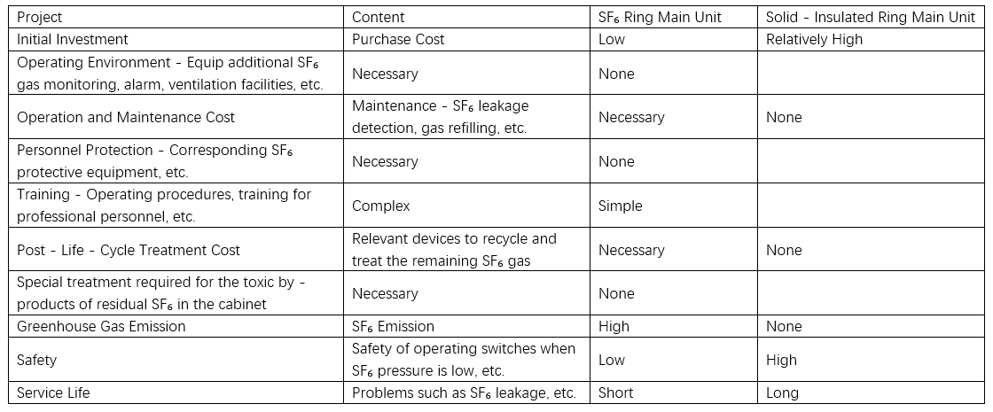
(4) Compact Structure. Designed to be as compact as possible while ensuring safety and ease of operation, these units have a smaller footprint and volume than even SF₆ RMUs, helping users save space and achieve direct economic benefits.
(5) Internal Arc Fault Resistance, Enhanced Safety and Reliability. According to Exnis reports, significant losses due to internal arcing in primary and secondary switchgear occur at least once annually. Most solid-insulated RMUs incorporate arc-resistant designs that minimize the impact of internal arcs, ensuring safer and more reliable operation.
(6) Visible Isolation Gaps. Equipped with observation windows, these units allow direct visual inspection of the three-position disconnect switch contacts, ensuring visible break points and enhancing operator safety.
(7) Intelligent Capabilities. Solid-insulated RMUs are more readily adaptable to distribution automation. By installing distribution terminal units (DTUs) and communication devices, functions such as status monitoring, remote control ("four-remote" functions), communication, self-diagnosis, and event logging can be easily implemented.
3.2 Current Application Status
Currently, the widespread adoption of solid-insulated RMUs is constrained by their relatively high cost and complex manufacturing processes. Their production requires higher technical precision than SF₆-insulated RMUs. Inadequate manufacturing techniques can lead to greater insulation risks, higher failure probabilities, and increased hazards compared to SF₆ RMUs, necessitating strict control over raw material quality and process standards. Additionally, the wiring configurations of solid-insulated RMUs are less flexible, particularly for functional units such as potential transformer (PT) cabinets and metering cabinets, offering limited options and restricting their application and development.
With continuous optimization of production processes and increasing standardization, the quality of solid-insulated RMUs is becoming more stable, and prices are gradually decreasing. Some countries offer 5%–10% incentives for products that do not use SF₆ to reduce emissions. This encourages users to consider total lifecycle costs rather than just initial purchase price. Drawing from international practices, solid-insulated RMUs can be prioritized in environmentally sensitive or new projects—such as residential communities, public buildings, and municipal infrastructure—while gradually phasing out SF₆ RMUs.
Aging or end-of-life SF₆ RMUs can be systematically replaced based on manufacturer-specified service life. Subsidies for users adopting eco-friendly solid-insulated RMUs can further support lifecycle cost considerations, promote product adoption, and advance environmentally responsible technologies. As environmental awareness grows, solid-insulated RMUs, as one of the alternatives to SF₆ RMUs, will gradually replace a portion of existing SF₆ units and gain widespread application, demonstrating strong market potential.
4 Conclusion
Solid-insulated RMUs are technologically comparable to SF₆ RMUs and possess unique advantages such as zero harmful emissions, truly maintenance-free operation, and lower total lifecycle costs, making them increasingly attractive to users. The State Grid Corporation of China's "First Catalog of Key New Technologies for Priority Promotion" (2011) stated that, considering trends toward higher technical reliability and stricter environmental requirements, solid-insulated RMUs are poised to fully replace SF₆ RMUs.
Furthermore, the "Technical Specification for 12 kV Solid-Insulated Ring Main Units" issued by the State Grid Corporation in 2012 affirmed that solid-insulated RMUs are technically capable of meeting complex operational demands and represent a new direction in RMU development, warranting active promotion. This marks formal recognition of solid-insulated RMUs by the industry and technical community. As a viable alternative to SF₆ RMUs, solid-insulated RMUs will gradually replace a portion of existing SF₆ units, achieving broad application and demonstrating excellent prospects for future development.


