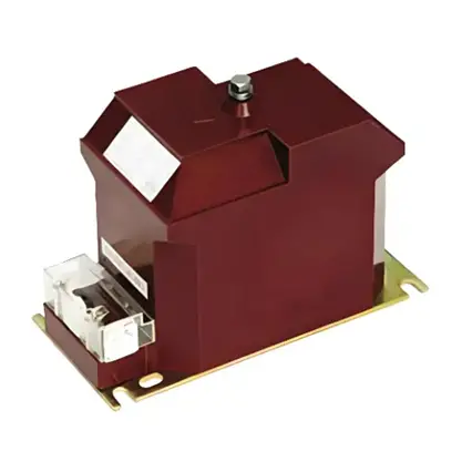
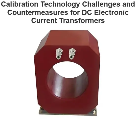
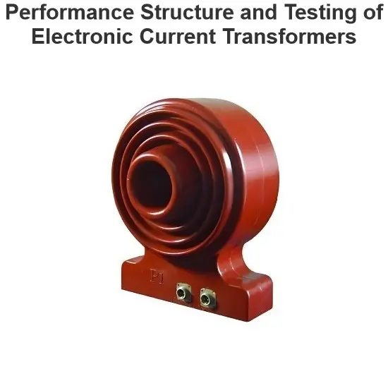
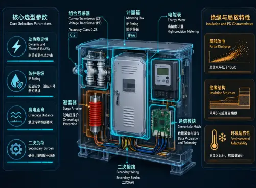
An outdoor metering unit typically consists of combined instrument transformers, an energy meter, a metering cabinet, surge arresters, secondary wiring, and communication modules. Selection should not be based only on accuracy class and price. It should be evaluated comprehensively from seven aspects: metering purpose, system parameters, load characteristics, insulation environment, secondary burden, dynamic and thermal stability, and communication and O&M.
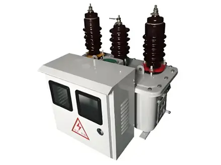
Pole-mounted metering unit
1. Confirm the Metering Point Purpose
| Metering Point Type |
Recommended Configuration |
Notes |
| Tie-line / Trade settlement |
CT 0.2S, PT 0.2 |
Strictest error requirements; complete acceptance documentation required |
| Grid-connection metering |
CT 0.2S, PT 0.2 |
Bidirectional metering and four-quadrant reactive energy required |
| Feeder assessment |
CT 0.2S/0.5S, PT 0.2/0.5 |
Balance between accuracy and cost |
| Internal monitoring |
CT 0.5, PT 0.5 |
Suitable for station service and load statistics |
| Distributed generation |
CT 0.2S, PT 0.2 |
Must accommodate reverse power flow and low-load conditions |
For electricity billing, grid-connection settlement, or tie-line assessment, the current transformer should preferably be class 0.2S, and the voltage transformer should preferably be class 0.2.
A conventional class 0.2 CT may show larger errors under low-load conditions. A class 0.2S CT maintains more stable accuracy over a wide load range, typically covering low-load conditions up to 120% of rated current. The exact range shall be subject to the applicable standards and equipment nameplate.
2. Check System Voltage, Frequency, and Connection Method
The outdoor metering unit must match the system parameters:
- Rated voltage: Common ratings include 6 kV, 10 kV, 24 kV, and 35 kV. Selection shall be based on the maximum system operating voltage.
- Rated frequency: 50 Hz is common in China; for export or overseas projects, 50 Hz or 60 Hz must be confirmed.
- Connection method: V/V connection is commonly used for three-phase three-wire systems. For three-phase four-wire systems or where zero-sequence voltage monitoring is required, Y/Y0 connection or an additional open-delta winding should be used.
- Bidirectional power flow: For PV, energy storage, and small hydropower grid-connection applications, the energy meter should support forward/reverse active energy, four-quadrant reactive energy, and time-of-use metering.
3. Select the Installation Type
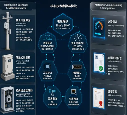
| Type |
Application |
Key Considerations |
| Pole-mounted metering unit |
10 kV overhead lines, small stations |
Small footprint, but overhead maintenance is inconvenient |
| Floor-standing metering cabinet |
Substations, box-type substations, tie-line points |
Easy maintenance; foundation and anti-condensation must be checked |
| Cabinet-type combined instrument transformer |
Switchgear, prefabricated substations |
Compact structure; secondary burden and heat dissipation must be checked |
| Electronic CT / Rogowski coil |
Impact loads, heavy harmonics, wide dynamic range |
Better dynamic response; project acceptance feasibility must be confirmed in advance |
Outdoor equipment is exposed to the environment for long periods. Special attention should be paid to the sealing of secondary terminal boxes, the enclosure IP rating, and rainproof and anti-condensation design. Rainwater and day-night condensation entering secondary terminals are common causes of insulation degradation and metering abnormalities.
4. Check Insulation and Environmental Adaptability
Outdoor metering units shall be selected according to site conditions and should not be treated as indoor products.
The following shall be confirmed:
- Ambient temperature range;
- Altitude: for installations above 1,000 m, insulation, temperature rise, and creepage distance shall be corrected in accordance with IEC 61869, GB/T, and other applicable standards;
- Pollution level: coastal, salt fog, industrial, and heavy dust areas require pollution-resistant designs and increased creepage distance;
- Insulation material: outdoor-grade epoxy resin or silicone rubber cast structures are preferred;
- IP rating: metering cabinets, terminal boxes, and cable entries shall meet rainproof and dustproof requirements;
- Enclosure material: stainless steel, hot-dip galvanized steel, or weather-resistant aluminum alloy is preferred.
5. Current Transformer Selection
- Accuracy class: Class 0.2S is preferred for trade settlement, tie-line, and grid-connection metering; class 0.5 may be used for internal monitoring.
- Ratio: The primary rated current shall be greater than the maximum continuous operating current, and the normal operating current should preferably fall within the optimal range of the rated current.
- Secondary current: 5 A or 1 A is commonly used. For long secondary cables, the secondary burden should be checked first, and 1 A may be selected when necessary.
- Rated secondary burden: The actual burden includes the energy meter, data acquisition terminal, terminal block, and cable impedance, and shall not exceed the CT rated burden.
- Dynamic and thermal stability: Short-time thermal current and dynamic stability current shall be verified against the system short-circuit capacity.
- Separate windings: The metering winding shall be separated from protection and measurement windings to prevent protection operations from affecting metering.
- Bidirectional metering: For grid-connection applications, it shall be confirmed that the CT maintains its accuracy under reverse power flow.
6. Voltage Transformer Selection
- Accuracy class: Class 0.2 is preferred for tie-line metering; class 0.5 may be used for non-settlement monitoring.
- Rated secondary voltage: Common values include 100 V, 100/√3 V, 110 V, 115 V, and 120 V, and shall match the energy meter, local utility requirements, and project standards.
- Secondary burden: The actual burden shall not exceed the PT rated output.
- Voltage factor: The continuous voltage factor and short-time overvoltage capability shall be confirmed.
- Ferroresonance: For isolated neutral or arc-suppression coil grounded systems, ferroresonance risk shall be assessed and suppression measures shall be provided.
- Secondary protection: The PT secondary circuit shall not be short-circuited. Fuses, miniature circuit breakers, or test terminals shall be provided.
7. Energy Meter and Communication Configuration
The energy meter shall match the instrument transformer accuracy class, connection method, and settlement rules:
- Active energy accuracy: class 0.2S or 0.5S;
- Reactive energy accuracy: typically class 2.0;
- Support for forward/reverse active energy and four-quadrant reactive energy;
- Support for time-of-use tariff, maximum demand, voltage loss, current loss, phase loss, reverse phase sequence, and cover-opening event recording;
- Communication interfaces shall meet remote meter reading and O&M requirements, such as RS485, 4G, and Ethernet; for overseas projects, DLMS/COSEM, Modbus, IEC 61850, or other protocols may be selected as required, subject to the project tender documents, owner specifications, and local utility requirements;
- Data encryption, sealing, and tamper-proof functions shall be provided.
If the metering point participates in power market trading, spot settlement, or renewable energy grid-connection assessment, the energy meter should also support high-frequency data acquisition, time-stamped records, and data traceability.
8. Secondary Circuits and Installation Acceptance
The following shall be checked during installation and commissioning:
- The CT secondary circuit shall not be open-circuited; the PT secondary circuit shall not be short-circuited;
- The secondary cable cross-section shall be verified based on voltage drop and burden;
- Test terminals or joint connection blocks should be provided in metering circuits to facilitate live testing and periodic verification;
- Phase sequence shall be correct, and positive phase sequence connection is preferred;
- Surge arresters of the corresponding voltage level shall be installed on the high-voltage incoming side;
- Seals, anti-tampering measures, and anti-opening protection shall be confirmed before acceptance.
After commissioning, periodic verification shall be carried out in accordance with local metering regulations and verification procedures. The verification interval shall follow the requirements of the utility, metrology authority, or project location.
9. Recommended Acceptance Documentation Checklist
During procurement or acceptance, the following items should be checked:
- System voltage, frequency, and grounding method;
- Metering point category and accuracy requirements;
- Installation method and environmental conditions;
- CT accuracy class, ratio, secondary current, rated burden, and dynamic/thermal stability;
- PT accuracy class, rated voltage, secondary burden, voltage factor, and resonance suppression measures;
- Energy meter functions, communication protocol, anti-tampering, and event recording;
- Insulation level, pollution level, creepage distance, and IP rating;
- Enclosure material, sealing structure, anti-condensation, and UV resistance;
- Secondary circuit voltage drop, wiring method, and test terminal configuration;
- Type test reports, factory test reports, metrological verification certificates or accuracy calibration reports, and insulation test data; partial discharge test data shall generally be provided for solid-insulated instrument transformers at 35 kV and above, while for 10 kV and below the requirements shall follow project specifications or local acceptance rules; confirmation of metering winding independence.
Edited From:Garca

 Login