• Product
  • Suppliers
  • Manufacturers
  • Solutions
  • Free tools
  • Knowledges
  • Experts
  • Communities
Search


Core Differences Between Current Transformers(CT)and Voltage Transformers(VT)

Rockwill
Field: Manufacturing
10Year<
China
 
In the vast network of a power system, current transformers (CT) and voltage transformers (PT/VT) serve as indispensable sensing devices. Both operate on the principle of electromagnetic induction, converting high voltage and high current on the primary side into low voltage and low current on the secondary side at a defined ratio, thereby providing safe and standardised signals for measuring instruments and protective relays. Although they share the same fundamental physical principles, their design philosophy, operating state, and safety practices differ dramatically in practical engineering applications.

I. Functional Role and Connection Method

The primary difference lies in their functional role and how they are connected to the power circuit:

  • Current Transformer (CT) — series-connected for current measurement: A CT must be connected in series with the primary power circuit. With very few primary turns (sometimes just a single through-type copper bar or bushing), the full load current of the line flows through the primary winding. The primary current is entirely determined by the external system load and is independent of the secondary-side condition.

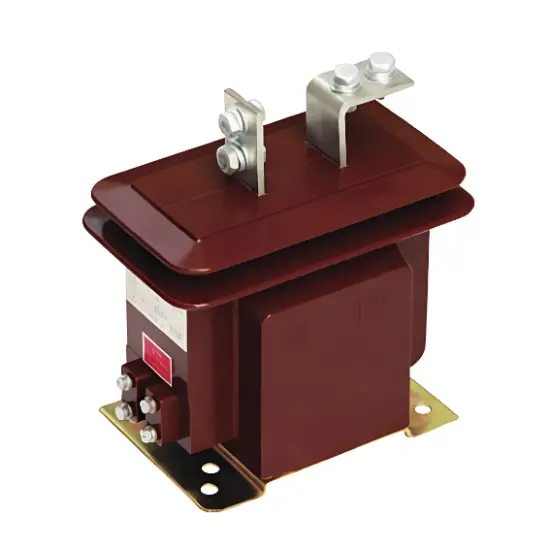
Cast Insulated Pillar Type Current Transformer 10kV-35KV

Cast Insulated Pillar Type Current Transformer

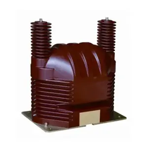
  • Voltage Transformer (PT/VT) — parallel-connected for voltage measurement: A PT must be connected in parallel between phases or between phase and earth on the busbar or line. Its primary winding has a large number of turns with a fine wire gauge and is subjected to the full system voltage. The primary voltage is determined by the power grid.

  • Cardinal rule: In short, CT is series-connected for current measurement; PT is parallel-connected for voltage measurement. Swapping their connection methods is an absolute violation that must never occur.

II. Operating State and Fatal Safety Prohibitions

Because of their fundamentally different connection methods, their normal operating states are diametrically opposite, giving rise to strictly enforced safety prohibitions:

  • CT — near-short-circuit state with open-circuit prohibition: Under normal operation, the instruments connected to the CT secondary present a very low impedance, keeping the secondary loop in a closed near-short-circuit state. Therefore, the CT secondary must never be opened while energised. If the secondary circuit is opened, the entire primary current is diverted to magnetisation, causing the core to saturate rapidly with severe residual magnetism. A sharp voltage spike is then induced in the secondary winding, reaching several thousand or even tens of thousands of volts, which can puncture insulation, destroy equipment, and pose a lethal threat to operating personnel.

  • PT — near-no-load state with short-circuit prohibition: The PT secondary is connected to high-impedance voltage coils, so under normal operation it operates in a near-no-load state. Therefore, the PT secondary must never be short-circuited while energised. Because the internal impedance of the PT secondary is very low, a short-circuit on the secondary side will instantly produce a short-circuit current tens of times the rated value, directly burning out the transformer windings.

iee-business

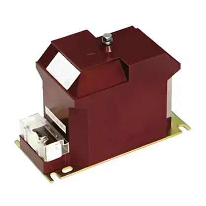
Indoor Single-phase grounding protection voltage transformer

  • Practical safety rules: Before working on a CT, the secondary terminals must first be short-circuited before disconnecting any wires. Before working on a PT, the secondary load must first be disconnected and the absence of voltage verified. These two rules are fundamental safety principles that all power operation and maintenance personnel must commit to memory.

III. Structural Design, Accuracy Classification, and Non-interchangeability

The differences in internal construction, accuracy systems, and interchangeability are equally pronounced:

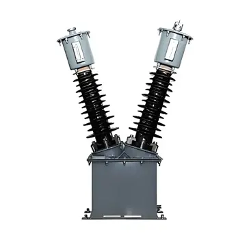
  • Physical appearance and internal structure: A CT has few primary turns with a thick conductor, a relatively compact size, and often a visible window for the primary conductor. A PT has many primary turns with a fine conductor, and its porcelain bushing tends to be longer at higher voltage ratings to increase creepage distance.

  • Accuracy classification: CT measuring accuracy classes (e.g. 0.2S, 0.5S) focus on ratio error and phase displacement across a wide current range, while CT protection classes (e.g. 5P, 10P) emphasise the accuracy limit factor (ALF) and composite error under short-circuit conditions. PT accuracy classes (e.g. 0.2, 0.5) focus on voltage ratio error and phase displacement at rated voltage.

  • Consequence of using a CT as a PT: If a CT is mistakenly connected in parallel to a high-voltage line as a PT, its very few primary turns will draw an extreme magnetising current, causing the core to saturate so severely that the device may explode instantly.

  • Consequence of using a PT as a CT: If a PT is mistakenly connected in series with the main circuit as a CT, its fine winding cannot withstand the high current and will overheat severely and burn out. The two devices are absolutely not interchangeable under any circumstances.

Summary

Current transformers (CT) and voltage transformers (PT/VT) are both fundamental sensing devices in the power system, yet they exhibit three distinguishing characteristics in practice: series current versus parallel voltage, opposite safety prohibitions, and fundamentally different construction.

  • Connection principle: CT is connected in series with the main circuit for current measurement; PT is connected in parallel across the busbar for voltage measurement.
  • Safety rules: CT secondary must never be opened (prevents lethal high-voltage breakdown); PT secondary must never be short-circuited (prevents overcurrent burnout).
  • Engineering bottom line: Their construction and impedance are fundamentally different; they are absolutely not interchangeable.

In engineering practice, these operation and maintenance rules are essential for reliable equipment operation, personnel safety, and power grid stability.

Edited From:Garca

Give a tip and encourage the author!

Comments

Share your question or perspective
WhatsApp
Send inquiry
+86
Click to upload file
Download
Get the IEE Business Application
Use the IEE-Business app to find equipment, obtain solutions, connect with experts, and participate in industry collaboration anytime, anywhere—fully supporting the development of your power projects and business.
Login
or continue with
New here?
Register