• Product
  • Suppliers
  • Manufacturers
  • Solutions
  • Free tools
  • Knowledges
  • Experts
  • Communities
Search


Rockwill Transformer Manufacturing Experience — Core Selection for Diverse Standard Requirements

Rockwill
Field: Manufacturing
10Year<
China
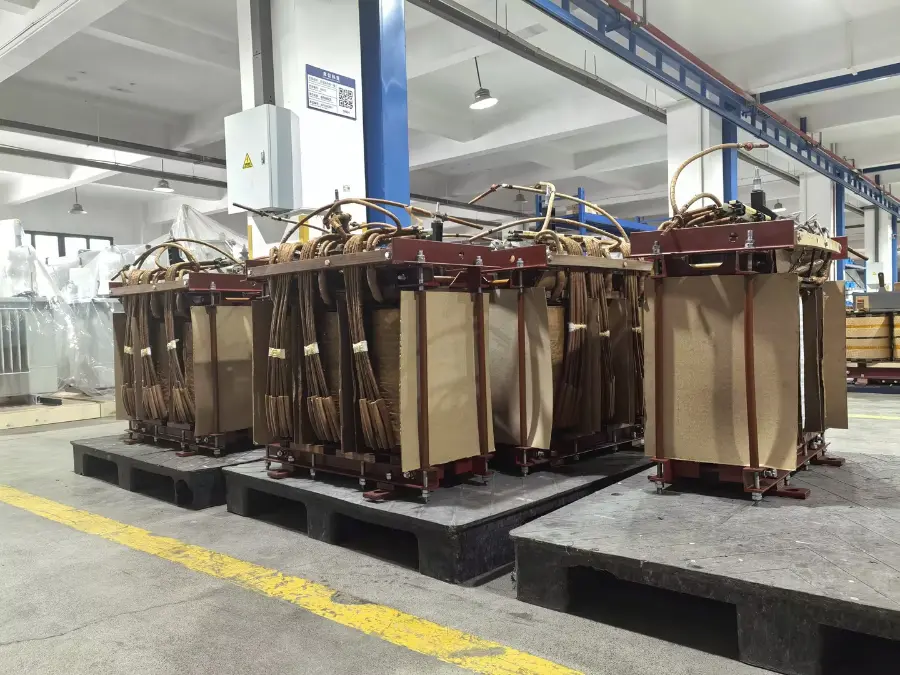
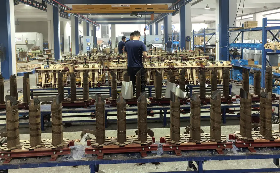
When faced with different standard systems (IEC, IEEE, GB, etc.) and special application scenarios such as photovoltaic, wind power, and rail transit, Rockwill has developed a systematic methodology for transformer core selection. The core idea: parameterize standard requirements into precise constraints on core material, structure, flux density, and manufacturing process. This is not simply a matter of stacking materials, but a rigorous engineering decision based on data-driven analysis — ultimately delivering compliant, reliable, and cost-optimized transformer core solutions to global customers.
iee-business

Energy Efficiency Class as the Guide — Precision Matching of Silicon Steel Grade and Thickness

  • Different standards impose vastly different no-load loss requirements, making this the first hard constraint in core selection.
  • For China's GB 20052-2020 distribution transformer energy efficiency standard, the new efficiency classes are very stringent, especially Levels 1 and 2. To achieve such low losses, Rockwill uses 0.20 mm or 0.23 mm ultra-thin Hi-B laser-scribed silicon steel (e.g., 23QH080, 20QH070), or directly recommends amorphous alloy cores. Amorphous alloy no-load loss is only about 1/3 that of conventional silicon steel, making it one of the most economical paths to meet Level 1 efficiency for oil-immersed distribution transformers.
  • For EU EcoDesign Tier 2, whose loss limits are slightly looser than China's Level 3, Rockwill typically selects 0.23 mm or 0.27 mm high-quality Hi-B silicon steel with step-lap joints, meeting requirements at reasonable cost.
  • For the US DOE 2016 efficiency standard, which emphasizes overall efficiency, we typically use high-permeability, low-loss 0.23 mm Hi-B silicon steel with flux density specifically optimized for 60 Hz operation.
  • In practice, Rockwill has built a cross-reference database of loss limits for major global energy efficiency standards. By inputting the rated capacity and voltage class, the system automatically recommends the lowest-cost compliant steel grade.

Noise Requirements Drive Core Structure and Operating Flux Density

Noise limits directly drive innovation in core structure.

  • For low-noise applications — residential areas requiring <45 dB, EU Noise Directive compliance, etc. — magnetostriction is the primary noise source. Rockwill addresses this from three angles:
  • First, select low-magnetostriction materials and ensure the Hi-B silicon steel annealing process fully relieves stress. Second, change the core structure, prioritizing wound cores (three-dimensional or planar). Wound cores have no overlapping joints, lower no-load current, and can reduce noise by 5–8 dB(A) compared to stacked cores. For projects with extremely demanding noise requirements, three-dimensional wound cores can easily keep noise below 38 dB(A). Third, reduce the operating flux density, lowering it from the conventional 1.7 T to 1.55–1.6 T. This increases core cross-section and cost, but is a necessary compromise in noise-sensitive applications.
  • For general industrial applications complying with IEC 60076-10 and similar standards, step-lap stacked cores with moderate flux density meet most requirements at the best cost-performance ratio.

iee-business

Harmonic and Special Loads — Flux Density Margin and Thinner Laminations

Applications such as PV inverters, wind power converters, and electric arc furnaces have high harmonic content. Relevant standards require transformers to withstand the additional losses and overheating caused by harmonic currents. Based on IEEE C57.159, IEC 60076-16, GB/T 36292, etc., Rockwill's countermeasures include:

  • Reserving over-excitation margin: designing the rated flux density conservatively (e.g., 1.60–1.65 T) to prevent core saturation from harmonic voltages.
  • Using thinner laminations: preferring 0.23 mm or even 0.20 mm silicon steel to reduce eddy current losses induced by high-frequency harmonics.
  • Embedding fiber optic temperature sensors in core hot spots to ensure core temperature rise stays within the insulation thermal class under full-load harmonic conditions.

iee-business

Adapting to Size and Transport Constraints — Optimizing Core Geometry

  • Offshore wind turbine towers, urban underground substations, and similar scenarios impose strict limits on transformer dimensions.
  • When height is constrained (e.g., offshore wind tower applications), a five-limb core or wound core is often used. The five-limb design significantly reduces the upper and lower yoke height, cutting transport height by 10–15%. Wound cores also offer high space factor and reduced volume. In these cases, higher-grade silicon steel is selected to compensate for the potential loss increase from reduced yoke cross-section.
  • When weight is constrained, silicon steel selection trends toward thinner, lower-loss grades, because at the same flux density a smaller core cross-section can be designed, reducing total weight.

Differentiating 50 Hz and 60 Hz Design — Dedicated Engineering

  • Core loss is proportional to frequency raised to the 1.6th power, so losses at 60 Hz are significantly higher than at 50 Hz. Rockwill maintains independent magnetization and loss curve databases for the North American (60 Hz) and Eurasian (50 Hz) markets.
  • When designing a 60 Hz transformer, we never simply apply a 50 Hz core design. Instead, we precisely control no-load loss by fine-tuning flux density or selecting the next thinner grade of silicon steel, meeting DOE or IEC efficiency requirements at each frequency.

Core Structure Customization for Specific Product Standards

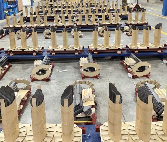
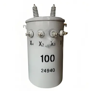
For US-style single-phase cylindrical transformers designed to IEEE C57.12.20 and DOE standards, the cylindrical tank and compact structure require a core that achieves extremely low loss and high reliability within a limited space. Rockwill typically selects high-quality Hi-B silicon steel rectangular wound cores, leveraging their joint-free construction and high space factor to perfectly match the cylindrical coil. This meets US standards for overload capacity and short-circuit strength while keeping no-load loss at very low levels.

For applications that need to remain compatible with existing lamination processes, a fully mitered, five-step shell-type stacked core is used, achieving low noise and uniform flux distribution within the cylindrical structure.

10kv单相25kVA极式配电变压器

10kV Single Phase 25 kVA Pole Mounted Electric Distribution Transformer


Rockwill Transformer Core Selection Decision Process

For every new transformer project, engineers follow a rigorous path:

  • Receive project standard requirements — identify no-load/load loss limits, noise level limits, product type and special operating conditions, size/weight constraints, and frequency.
  • Preliminary material selection — choose silicon steel grade or amorphous alloy based on loss limits.
  • Determine core structure based on product type and noise requirements — rectangular wound core or shell-type stacked core for US-style cylindrical transformers; wound core for very low noise in conventional distribution transformers, otherwise stacked core with step-lap joints.
  • Adjust core cross-section or limb count to meet size and weight constraints.
  • Verify flux density margin and eddy current heating for special operating conditions.
  • Perform electromagnetic field simulation for parameter optimization after preliminary design.
  • Finalize core design.
 

Summary

At Rockwill, transformer core selection is a systematic engineering process that translates abstract standards (IEC, IEEE, GB) — together with the specific requirements of each product type — into the four technical dimensions of material, flux density, structure, and process, ultimately balancing technical compliance, operational reliability, and cost control.

Edited From:Leon

Give a tip and encourage the author!
Topics:

Comments

Share your question or perspective
WhatsApp
Send inquiry
+86
Click to upload file
Download
Get the IEE Business Application
Use the IEE-Business app to find equipment, obtain solutions, connect with experts, and participate in industry collaboration anytime, anywhere—fully supporting the development of your power projects and business.
Login
or continue with
New here?
Register