In the field of distribution transformers, although 30kV, 33kV, and 35kV appear close in terms of system nominal voltage, there are clear hierarchical differences in the classification of highest voltage for equipment (Um) and the corresponding internal and external insulation designs.
From the perspective of the insulation coordination systems of the International Electrotechnical Commission (IEC) and Chinese national standards (GB):
-
30kV and 33kV: Typically belong to the same insulation class, with their highest voltage for equipment Um = 36kV.
-
35kV: Enters a higher insulation class, with its highest voltage for equipment Um = 40.5kV.
Therefore, the differences among these three are mainly reflected in the cross-level disparity between 35kV equipment and 30/33kV equipment. The following analysis examines these differences from the perspectives of external and internal insulation.
I. Differences in Test Standards (Core Basis for Insulation Design)
Whether for internal or external insulation, the selection of dimensions and materials directly depends on two core withstand voltage test indicators:
-
30kV / 33kV (Um = 36kV):
-
35kV (Um = 40.5kV):
-
Rated lightning impulse withstand voltage (BIL): 200 kV (some special requirements may be higher)
-
Rated short-duration power frequency withstand voltage: 85 kV (or 95 kV, depending on the specific standard)
II. Differences from the External Insulation Perspective
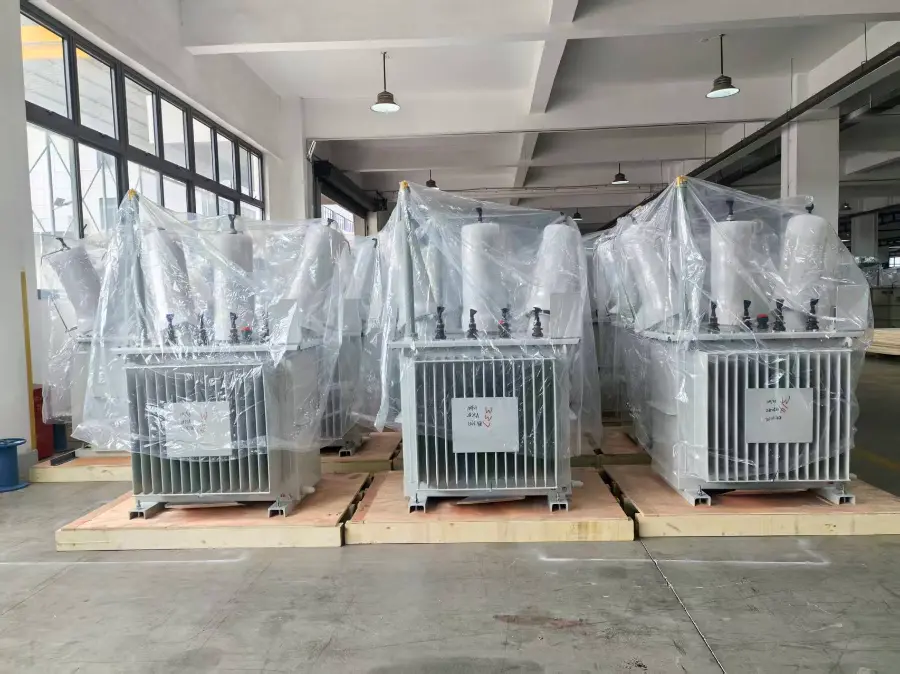
External insulation primarily refers to the parts of the transformer exposed to air, i.e., the high-voltage bushings and the insulation system formed by their surfaces and the surrounding air.
1. Larger Air Clearances (Safety Gaps)
-
To prevent air breakdown, the minimum air clearance requirements for phase-to-phase and phase-to-ground are greater for 35kV transformers than for 33kV transformers. For example, the air clearance between 33kV bushings is typically designed around 300mm, while for 35kV, it needs to be increased to 320mm-350mm or even more.
2. Longer Creepage Distance on Bushings
-
External insulation must resist pollution flashover (discharge on insulator surfaces under humid and contaminated conditions). Creepage distance = Unified specific creepage distance (e.g., 31 mm/kV) × Highest voltage for equipment (Um).
-
The minimum creepage distance for 33kV bushings is calculated based on 36kV (e.g., 31 × 36 = 1116 mm); whereas for 35kV, it is calculated based on 40.5kV (31 × 40.5 = 1255.5 mm). Consequently, the high-voltage bushings of 35kV transformers have longer physical dimensions, with more sheds or greater spacing between them.
3. Corona Prevention and Voltage Grading Design
-
As the voltage rises to the 40.5kV level, electric field distortion at the edges of external insulation fittings (such as the terminal connectors at the top of bushings) becomes more severe. The external insulation design for 35kV requires slightly higher requirements for the smoothness of fitting chamfers compared to 30/33kV to prevent corona discharge.
III. Differences from the Internal Insulation Perspective
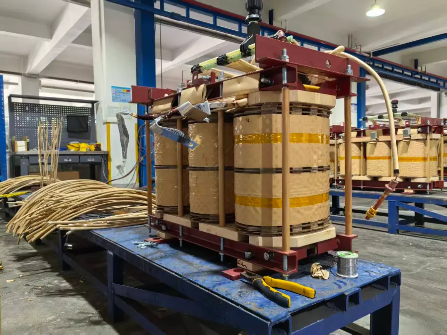
Internal insulation mainly refers to the insulation system inside the transformer tank, typically consisting of transformer oil, insulating paper, laminated wood, pressboard, etc. (for dry-type transformers, epoxy resin casting). Differences in internal insulation directly affect the transformer core window height, coil dimensions, and overall cost.
1. Increased Main Insulation Dimensions (Winding-to-Ground, Winding-to-Winding)
-
Main insulation thickness: To withstand the 200kV lightning impulse (30kV higher than for 33kV), the thickness of the pressboard cylinder between the high and low voltage windings of a 35kV transformer, as well as the width of the main oil duct, must be increased.
-
Insulation distances (Margins): The distance from the ends of the high-voltage winding to the upper and lower yokes of the core, and the oil gap distance from the outermost layer of the high-voltage winding to the inner wall of the transformer tank, must all be designed more generously for 35kV than for 30/33kV; otherwise, the withstand voltage tests cannot be passed.
2. Enhanced Longitudinal Insulation (Turn-to-Turn, Layer-to-Layer, Section-to-Section)
-
When a lightning wave (170kV vs 200kV) strikes the transformer, the voltage is primarily distributed between turns and layers of the winding.
-
Therefore, the number of insulating paper layers wrapped around the high-voltage winding conductors of a 35kV transformer is typically greater than for 33kV; the thickness of the insulating pressboard between coil layers is also increased accordingly.
3. More Complex Electric Field Control Structures
-
Internal insulation is not merely about "adding thickness"; it also involves electric field distribution. To prevent partial discharge (PD) in the oil-paper insulation system, the ends of the 35kV coil (high field strength regions) typically require more angle rings and end rings for electrostatic field grading. Although 33kV designs also need these, the dimensional margins for these formed insulation components are more stringent in 35kV designs.
4. Tank Volume and Insulating Oil Quantity
-
Because all internal insulation distances are comprehensively increased (the coil becomes larger and the distance to the tank wall increases), the overall core of a 35kV transformer must be enlarged. Consequently, the tank volume and the amount of insulating oil required are significantly higher than for 30kV/33kV transformers of the same capacity.
Summary
From the perspective of manufacturing and insulation design:
-
30kV and 33kV are generally treated as the same insulation platform in engineering practice (36kV class). Manufacturers often use the 33kV design to accommodate 30kV orders, and there is virtually no substantial difference in insulation structure between the two.
-
35kV is an independent insulation platform (40.5kV class). Due to the step-change increase in lightning impulse withstand voltage from 170kV to 200kV, the internal insulation oil gaps and pressboard thicknesses, as well as the external insulation bushing lengths and air clearances, all require a step-change amplification. This is why, for the same capacity, the cost and volume of a 35kV transformer are typically significantly larger than those of a 33kV transformer.
Edited From:Echo

 Login