• Product
  • Suppliers
  • Manufacturers
  • Solutions
  • Free tools
  • Knowledges
  • Experts
  • Communities
Search


The Application of Reclosers and Sectionalizers in Distribution Network Automation

Echo
Echo
Field: Transformer Analysis
China

1. Selection of Reclosers and Sectionalizers

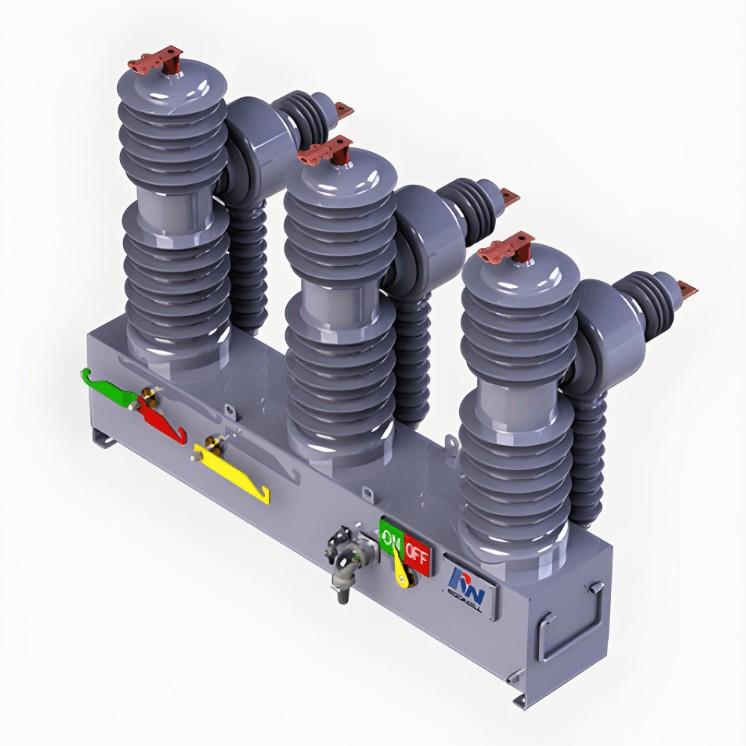
The selection of reclosers and sectionalizers is crucial for achieving distribution network automation. Sectionalizers cooperate with the upstream circuit breakers on the power supply side. They automatically trip when three conditions are simultaneously met: the fault current exceeds its set - value, the line undervoltage current is less than 300 mA, and the set number of counts is reached. Reclosers are applied in indoor substations or on outdoor poles. They enhance power supply reliability through multiple reclosing operations, identify fault areas, reduce the power - outage area, and miniaturize the information upload control system, thereby meeting the requirements of distribution network automation.

  • Install an outdoor high - voltage vacuum automatic recloser (with a permanent - magnet mechanism) at the substation outlet as the main line protection switch. This switch should be adjusted to perform two reclosing operations, one fast and two slow (it can also be adjusted according to specific needs).

  • Install sectionalizers with two - count functions at the entrances of large branches, and install sectionalizers with one - count functions at the entrances of small branches. This effectively isolates the terminal accident points, reduces the power - outage area, and optimizes their coordination.

  • Since the line protection adopts reclosing protection, it effectively ensures that the line can bypass transient faults, preventing more than 85% of transient faults from severely affecting the power supply quality.

  • When installing a recloser, calculate the short - circuit current and then adjust its activation value.

  • Reclosers are equipped with remote - operation interfaces, which provide sufficient room for future implementation of "four - remote" control (remote sensing, remote control, remote signaling, and remote metering).

  • For line grounding faults, reclosers have grounding - fault protection functions, but they can only protect the entire line. When a grounding fault occurs, the specific location of the fault cannot be determined. If a sectionalizer with grounding - fault protection function is selected, the cost is extremely high. It is recommended to use a grounding - fault receiver in the substation and grounding - fault indicators on the line. When a grounding fault occurs, the grounding - fault indicators on the line flip to indicate and send signals to determine the specific location, and the grounding - fault receiver in the substation receives the signals and gives an alarm.

  • To ensure good coordination between reclosers and sectionalizers, the originally installed pole - mounted vacuum circuit breakers on the line must be converted into load switches.

2. Example Illustration

Take the radial - structured power grid shown in Figure 1 as an example. Install sectionalizers with a count of 2 times at the entrances of large branches where the load is particularly heavy and the lines are relatively long, and install sectionalizers with a count of 1 time at the entrances of small branches. Set the recloser at the substation outlet to have an inverse - time characteristic with one fast and two slow operations. Install a sectionalizer F1 with a count of 2 times at the entrance of the L2 branch of line L1, and install a sectionalizer F2 with a count of 1 time at the L3 branch.

If a fault occurs in the L2 branch, the recloser at the substation outlet detects the fault current and acts quickly once. Since the sectionalizer F1 has not reached the set number of counts, it remains in the closed state. After a certain reclosing interval, the recloser at the substation outlet recloses. If it is a transient fault, the power supply to the line is restored after the recloser recloses. If it is a permanent fault, the outlet recloser trips again. The sectionalizer F1 reaches the set number of counts, drops, and trips, isolating the fault section. After the outlet recloser recloses again, the power supply to the other lines is restored.

This solution is applicable when the original pole - mounted circuit breakers cannot meet the requirements of distribution network automation. Adding reclosers and sectionalizers fully realizes the protection of 10 kV lines, is suitable for the construction and development of the power grid, and meets the requirements of distribution network automation.

Give a tip and encourage the author!
Recommended
3D Wound-Core Transformer: Future of Power Distribution
Technical Requirements and Development Trends for Distribution Transformers Low losses, especially low no-load losses; highlighting energy-saving performance. Low noise, particularly during no-load operation, to meet environmental protection standards. Fully sealed designto prevent transformer oil from contacting external air, enabling maintenance-free operation. Integrated protection devices within the tank, achieving miniaturization; reducing transformer size for easier on-site installation. C
Echo
10/20/2025
Reduce Downtime with Digital MV Circuit Breakers
Reduce Downtime with Digitized Medium-Voltage Switchgear and Circuit Breakers"Downtime" — it’s a word no facility manager wants to hear, especially when it’s unplanned. Now, thanks to next-generation medium-voltage (MV) circuit breakers and switchgear, you can leverage digital solutions to maximize uptime and system reliability.Modern MV switchgear and circuit breakers are equipped with embedded digital sensors that enable product-level equipment monitoring, providing real-time insights into the
Echo
10/18/2025
One Article to Understand the Contact Separation Stages of a Vacuum Circuit Breaker
Vacuum Circuit Breaker Contact Separation Stages: Arc Initiation, Arc Extinction, and OscillationStage 1: Initial Opening (Arc Initiation Phase, 0–3 mm)Modern theory confirms that the initial contact separation phase (0–3 mm) is critical to the interrupting performance of vacuum circuit breakers. At the beginning of contact separation, the arc current always transitions from a constricted mode to a diffused mode—the faster this transition, the better the interruption performance.Three measures c
Echo
10/16/2025
Advantages & Applications of Low-Voltage Vacuum Circuit Breakers
Low-Voltage Vacuum Circuit Breakers: Advantages, Application, and Technical ChallengesDue to their lower voltage rating, low-voltage vacuum circuit breakers have a smaller contact gap compared to medium-voltage types. Under such small gaps, transverse magnetic field (TMF) technology is superior to axial magnetic field (AMF) for interrupting high short-circuit currents. When interrupting large currents, the vacuum arc tends to concentrate into a constricted arc mode, where localized erosion zones
Echo
10/16/2025
Send inquiry
Download
Get the IEE Business Application
Use the IEE-Business app to find equipment, obtain solutions, connect with experts, and participate in industry collaboration anytime, anywhere—fully supporting the development of your power projects and business.