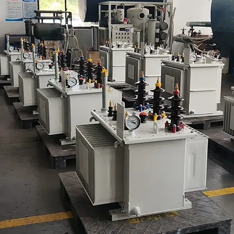
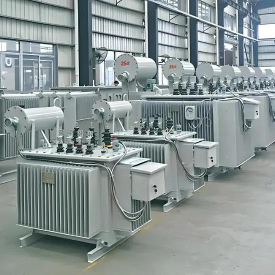
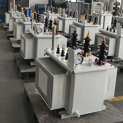
When an unloaded transformer is energized, it generates an inrush current. Repeated switching operations cause cumulative damage across several dimensions.
The Nature of Inrush Current
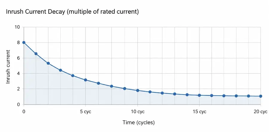
At the moment of energization, the core flux jumps from zero and — superimposed on residual magnetism — can reach 2–2.5× rated flux, driving peak inrush currents of 6–10× rated current or more, decaying over several cycles.
Primary Damage Mechanisms
① Cumulative Insulation Aging (most critical)
|
Mechanism
|
Description
|
|
Thermal stress
|
Joule heating from inrush current locally raises winding temperature each time
|
|
Electrical stress
|
High-voltage impulses trigger partial discharge events that carbonize insulation over time
|
|
Cumulative effect
|
Each individual operation may seem harmless, but repeated events progressively reduce dielectric strength until breakdown occurs
|
② Winding Mechanical Deformation
- Electromagnetic force on conductors scales as F∝I2F∝I2, so peak inrush creates axial and radial forces several times those seen in normal operation
- Repeated stress loosens conductors, spacers, and blocking — ultimately causing inter-turn or inter-layer short circuits
③ Core Over-Excitation Losses
- Saturated flux regions cause localized core overheating, degrading the insulating varnish between laminations
- Long-term accumulation leads to inter-lamination short circuits, increased no-load losses, and abnormal temperature rise
④ Switching Overvoltage Superposition
- Poor breaker timing (three-phase non-simultaneity, re-striking arcs) superimposes switching overvoltages on top of the inrush event
- Particularly damaging to low-voltage winding insulation and connected cables
⑤ Protection System and Breaker Fatigue
- Differential protection must repeatedly discriminate between inrush and fault current — increasing the risk of relay maloperation
- Each interruption of heavy current erodes breaker contacts; energization count directly converts to mechanical service life consumption
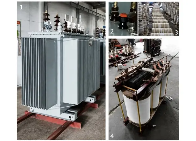
Vziman S-M Series Power Transformers
Engineering Recommendations
- Limit switching frequency — avoid repeated no-load energization; keep closings to ≤ 3–5 per day under normal circumstances
- Dissolved Gas Analysis (DGA) — take an oil sample after excessive switching events; watch for abnormal H₂ and C₂H₂ levels
- Manage residual flux — use a degaussing procedure or controlled closing angle to reduce inrush peak where possible
- Review protection settings — verify that differential relay inrush restraint (2nd-harmonic blocking ratio) is correctly calibrated to avoid maloperation
- Track breaker operations — log each energization and benchmark against the manufacturer's rated mechanical endurance for preventive maintenance
Summary
A single inrush current upon switching-on can be tolerated by transformers. However, the cumulative effect resulting from frequent switching operations will systematically shorten insulation service life and aggravate mechanical degradation of windings, constituting one of the common causes of abnormal transformer aging.
The core advantage of Vziman transformers lies in exceptional resistance to electrical shocks. By adopting higher-grade insulating materials, reinforced winding mechanical structures and optimized core design, they effectively suppress cumulative thermal, electrical and mechanical damages induced by frequent switching.
Consequently, under harsh operating conditions or scenarios requiring frequent switching, Vziman transformers deliver longer service life, lower failure rates and markedly superior power supply reliability compared with conventional products.

 Login
Login