Flexible AC Transmission Systems (FACTS) – What and why?
FACTS is the acronym for “Flexible AC Transmission Systems” and refers to a group of resources used to overcome certain limitations in the static and dynamic transmission capacity of electrical networks. The IEEE defines FACTS as alternating current transmission systems incorporating power-electronics based and other static controllers to enhance control ability and power transfer ability. The main purpose of these systems is to supply the network as quickly as possible with inductive or capacitive reactive power that is adapted to its particular requirements, while also improving transmission quality and the efficiency of the power transmission system.
Features of Flexible AC Transmission Systems (FACTS)
Fast voltage regulation,
Increased power transfer over long AC lines,
Damping of active power oscillations, and
Load flow control in meshed systems,
Thereby significantly improving the stability and performance of existing and future transmission systems.
That is, with Flexible AC Transmission Systems (FACTS), power companies will be able to utilize their existing transmission networks better, substantially increase the availability and reliability of their line networks, and improve both dynamic and transient network stability while ensuring a better quality of supply.
Influence of Reactive Power Flow on Power System Voltage

Reactive Power Compensation in Power Transmission System
Consumer load requires reactive power that varies continuously and increases transmission losses while affecting voltage in the transmission network. To prevent unacceptably high voltage fluctuations or the Reactive power compensation consumer load requires reactive power that varies continuously and increases transmission losses while affecting voltage in the transmission network.
To prevent unacceptably high voltage fluctuations or power failures that can result, this reactive power, must be compensated and kept in balance. The passive components such as reactors or capacitors, as well as combinations of the two that supply inductive or capacitive reactive power, can perform this function. The more quickly and precisely the reactive power compensation can accomplish, the more efficiently the various transmission characteristics can be controlled. For this reason, fast thyristor-switched and thyristor controlled components are replacing almost these slow mechanical switched components. Owner failures that can result, this reactive power must be compensated and kept in balance.
Effects of Reactive Power Flow
Reactive power flow has the following effects:
Increase in transmission system losses
Major influence on system voltage deviation
Limitation of power transfer
Steady-state and dynamic stability limits
Parallel and Series
Type |
Shor-circuit level |
Transmission phase angle |
Steady-state voltage |
Voltage after load rejection |
Application |
 |
nearly unchanged |
slightly increased |
increased |
high |
voltage stabilization at heavy load |
 |
nearly unchanged |
slightly increased |
decreased |
low |
voltage stabilization at light load |
 |
nearly unchanged |
controlled |
controlled |
limited by control |
fast voltage control reactive power control damping of power swings |
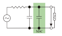
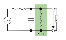
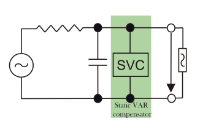
Fig. Shows today’s most common shunt compensation devices, their influence on the most important transmission parameters, and typical applications.

Fig.: The active power/ transmission angle equation illustrates which FACTS components selectively influence which transmission parameters.
Protection and Control of FACTS
To further improve redundancy management, we developed special modules that supplement the standard SIMATIC TDC automation system. Another new module in the instrumentation and control cabinet is responsible for issuing triggering signals to the thyristor valves. Altogether, SIMATIC TDC with its high integration density takes up significantly less space in the plant than the previous technology. Never the less, use of SIMATIC TDC is not limited to new FACTS. With its flexible interface design, it can easily replace existing systems. In this case, the measured values of existing plants are integrated into and further processed by the new control system. Because it requires so little space, by the new technology, we can even configure in parallel with the existing C and P system to integrate the FACTS with as little delay as possible.
 Human Machine Interface
The interface between the operator and the plant
(HMI = Human Machine Interface) is the standardized
SIMATIC Win CC visualization system, which further simplifies operation and facilitates the adaptation of graphical user interfaces to the operator’s requirements.
Hardware for Control and Protection
Siemens offers the latest in control and protection for FACTS – the tried and tested SIMATIC TDC (Technology and Drive Control) automation system. SIMATIC TDC is used worldwide in almost every industry and has been proven in both production and process engineering as well as in many HVDC and FACTS applications. Operating personnel and project planning engineers work exclusively with a standardized, universal hardware and software platform, enabling them to perform demanding tasks more rapidly. One of the main considerations in developing this automation system was to ensure the highest degree of availability of the FACTS – which is why all control and protection systems, as well as the communication links, are configured redundantly (if requested by the customer).
The new instrumentation and control technology also permits the use of a high-performance fault recorder operating at a 25 kHz sampling rate. New instrumentation and control technology reduces the period between fault recording and the printout of the fault report from several minutes (previously) to 10 seconds (now).
Converter for FACTS
LTT – Light Triggered Thyristors
Thyristors are a key element in controlling (switching on and off) the passive components in reactive power compensation systems. The system of direct light triggering developed by Siemens activates the thyristors with a pulse of light that lasts for 10 microseconds and has a peak power of 40 mill watts. The device also incorporates overvoltage protection, so that it is self-protecting if the forward voltage exceeds the maximum permitted limit. The light pulse is carried by fiber optics at ground potential directly from the valve control to the thyristor gate.
Conventional high-voltage thyristor valve technology uses electrically triggered thyristors, which need a pulse with a peak power of several watts. Electronic equipment placed alongside each thyristor generates this pulse. In turn, this electronic equipment, which needs an auxiliary power supply, is activated at ground potential by optical signals from the valve control. Substituting direct light triggering for this electronic equipment reduces the number of electrical and electronic components in the thyristor valve – and, consequently, the possibility of failure – by around 80 percent which improves reliability and eliminates problems associated with electromagnetic compatibility. The other important fact about the new thyristor technology is that long-term availability of electronic components for replacement purposes over a period of at least 30 years is no longer a problem.
Thyristor valves from Siemens are assembled from 4-inch or 5-inch thyristors, depending on the current- carrying capacity/rated current required. Thyristor technology has been under constant development since the early 1960s. At present, thyristors can safely and economically handle blocking voltages of up to 8-kilovolts and rated currents of up to 4,200 amperes.
Statement: Respect the original, good articles worth sharing, if there is infringement please contact delete.


