Definition and Basics of Electronic Relays
Definition: An electronic relay is an electronic switch that operates to open or close circuit contacts using electronic components, eliminating the need for any mechanical movement. In electrical systems, the current carrier pilot relaying scheme is commonly employed in these relays for the protection of transmission lines. This approach enables efficient and precise detection of faults, ensuring the safety and reliability of the power grid.
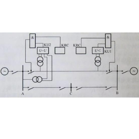
Electronic relays utilize electronic valves as their measuring units, which play a crucial role in monitoring electrical parameters. There are two fundamental configurations of electronic relays, as illustrated below. One configuration is based on an amplitude comparator, while the other relies on a phase comparator. Each setup has its unique advantages and is designed to suit different protection requirements within electrical systems.
Amplitude Comparator Electronic Relay
The figure depicting the amplitude comparator electronic relay is shown below. This relay receives two alternating current (AC) input quantities. These quantities are first compared and then rectified through a rectifier bridge circuit. The AC input is applied to the control grid of the bridge, which processes the electrical signals. The relay, connected in series with the bridge circuit, activates when the magnitude of one input quantity surpasses that of the other. This mechanism allows the relay to respond promptly to variations in electrical amplitudes, making it an effective component for fault detection and circuit protection.

Electronic Phase Comparator Relay Operation
In an electronic phase comparator relay, the two alternating current (AC) quantities are processed in a distinct manner. One AC quantity is fed into the control grid of the electronic tube, while the other is directly connected to the tube's screen. This unique setup forms the basis for phase - based signal analysis within the relay.
The relay's activation mechanism hinges on the phase relationship between these two AC quantities. Specifically, the relay initiates its operation precisely when the two AC quantities are in phase with each other. When this occurs, it indicates a particular electrical condition, which the relay is designed to detect and respond to. This phase - sensitive operation makes the electronic phase comparator relay highly effective for applications where accurately identifying in - phase conditions is crucial, such as in certain power system protection and monitoring scenarios.

Advantages and Disadvantages of Electronic Relays
Advantages of Electronic Relays
Electronic relays offer several notable benefits that contribute to their utility in various electrical applications:
Low Maintenance Requirements: Unlike traditional mechanical relays, electronic relays lack moving parts. This absence of physical components subject to wear and tear significantly reduces the need for frequent maintenance. As a result, electronic relays can operate for extended periods with minimal upkeep, lowering maintenance costs and improving system reliability.
Rapid Response Times: Electronic relays are designed to respond to electrical stimuli with exceptional speed. Their electronic - based switching mechanisms enable them to detect changes in electrical signals and activate or deactivate circuit contacts in a fraction of a second. This fast response time is crucial in applications where quick action is required to protect electrical equipment or maintain system stability.
Reduced Burden on Instrument Transformers: By virtue of their design, electronic relays draw less current compared to some other types of relays. This lower current draw results in a decreased burden on instrument transformers, allowing these transformers to operate more efficiently and potentially extending their lifespan. This advantage is particularly valuable in power systems where optimizing the performance of instrument transformers is essential for accurate measurement and reliable protection.
Disadvantages of Electronic Relays
Despite their advantages, electronic relays also have certain limitations that restrict their widespread use:
High - Tension Supply Requirement: Electronic relays typically demand a high - tension power supply for operation. This need for high - voltage input can pose challenges in terms of power system integration and safety. Specialized electrical infrastructure and safety measures may be required to provide the necessary high - tension supply, increasing the complexity and cost of implementing electronic relays in some applications.
High Power Consumption: Compared to some alternative relay technologies, electronic relays often consume a relatively large amount of electrical power. This high power consumption can be a significant drawback, especially in energy - conscious applications or systems where minimizing power usage is a priority. The increased power draw not only adds to operational costs but may also contribute to heat generation, potentially affecting the performance and lifespan of the relays.
Limited Lifespan: Although electronic relays are free from mechanical wear, they are still subject to component degradation over time due to factors such as electrical stress, temperature fluctuations, and aging of electronic components. As a result, electronic relays generally have a shorter lifespan compared to some more robust relay technologies. This limited lifespan can lead to more frequent replacements, increasing maintenance costs and potentially causing system disruptions.
Practical Limitations in Power Systems: Due to the combined factors of high - tension supply requirements, high power consumption, and limited lifespan, electronic relays have not found widespread practical use in power systems. These limitations often make them less attractive compared to other relay types that offer better performance, reliability, and cost - effectiveness in the demanding environment of power system protection and control.