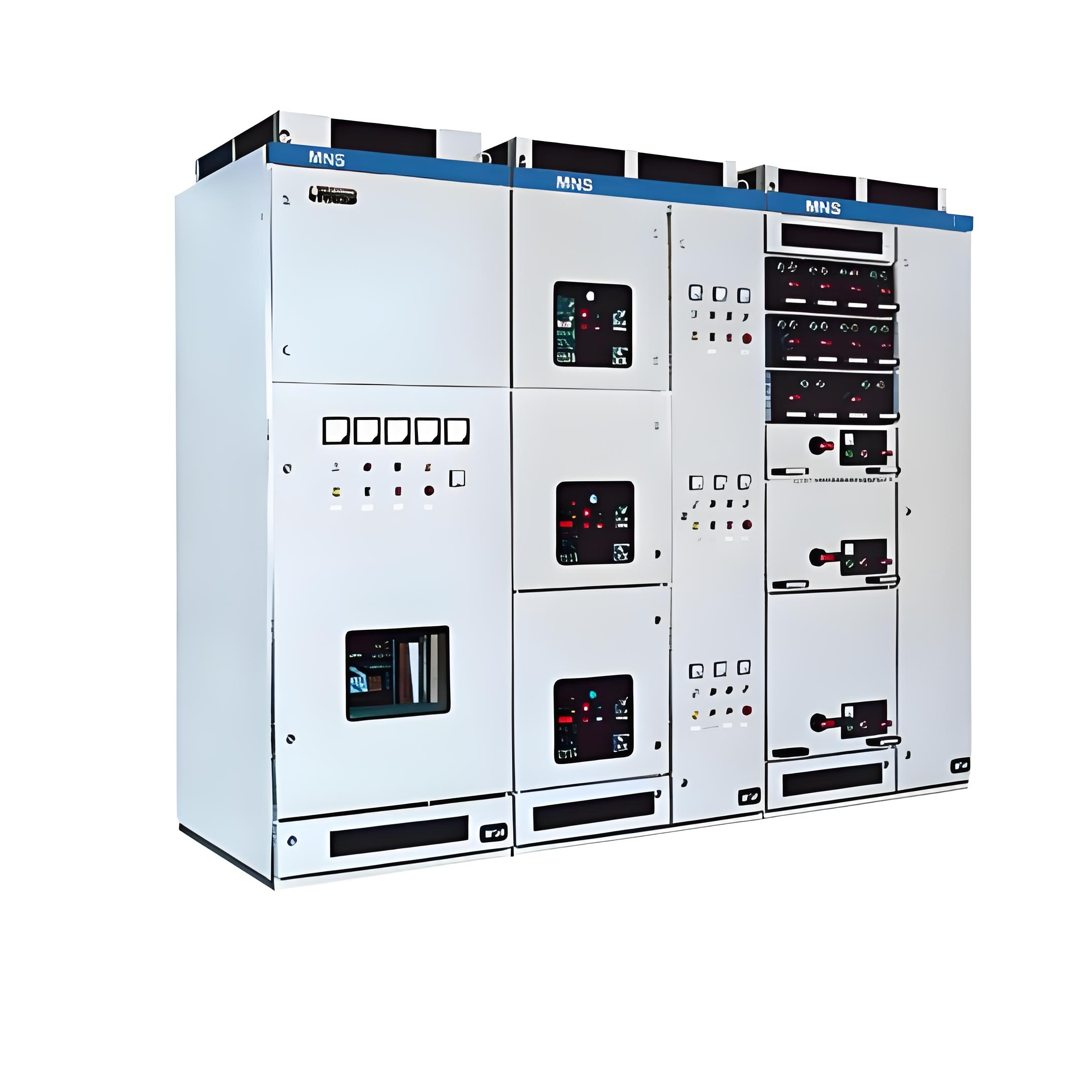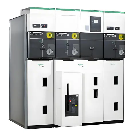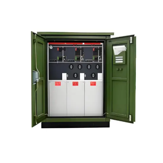
Photovoltaic (PV) Grid-Connection Cabinet
A photovoltaic (PV) grid-connection cabinet, also known as a PV grid-connection box or PV AC interface cabinet, is an electrical device used in solar photovoltaic power generation systems. It is primarily responsible for converting the direct current (DC) electricity generated by a PV system into alternating current (AC) and connecting it to the utility grid.
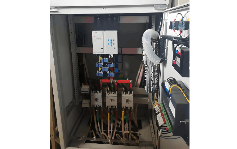
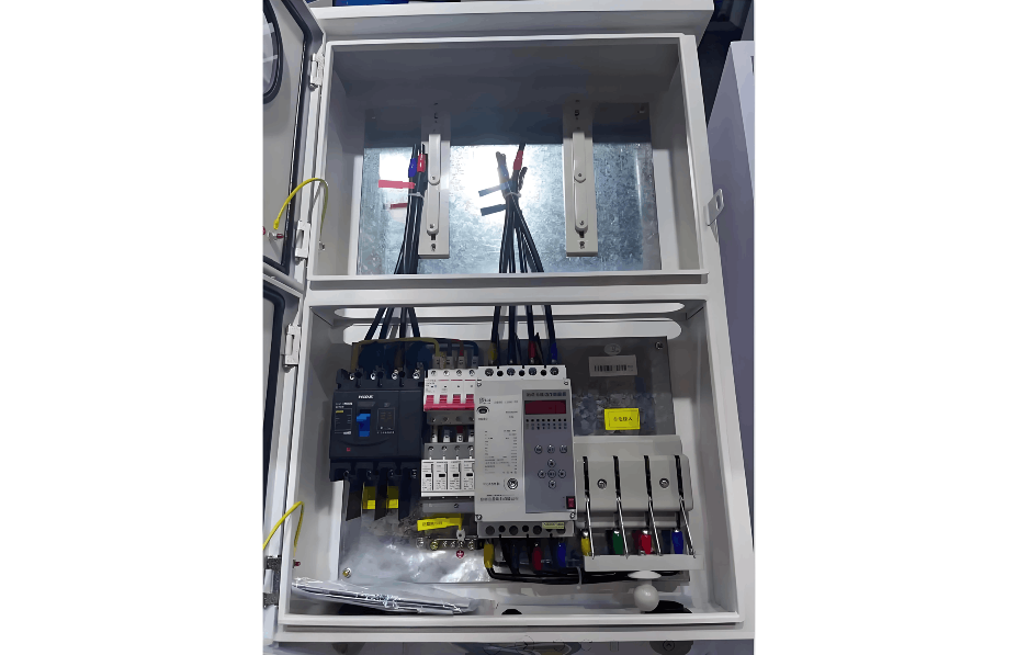
Main Components of a PV Grid-Connection Cabinet:
DC Input Terminals: Receive DC power generated by PV modules, typically connected via DC cables.
Inverter: Converts DC power into AC power. The inverter’s power rating, output voltage, and other parameters must be selected based on specific system requirements.
AC Output Terminals: Connect the AC power output from the inverter to the grid through AC switching devices, enabling grid synchronization.
Protection Devices: The cabinet typically includes various protective components such as overcurrent protection, overvoltage protection, and short-circuit protection to ensure safe and stable system operation.
Control and Monitoring Devices: Equipped with control and monitoring systems to supervise and manage the operational status, measure and record electrical parameters, and enable remote monitoring and management functions.
In summary, the PV grid-connection cabinet plays a crucial role in converting DC power from the photovoltaic system into AC power and integrating it with the grid. It is one of the key electrical components in a photovoltaic power generation system.
II. Testing of PV Grid-Connection Cabinets
Testing of PV grid-connection cabinets is conducted to verify that their performance and functionality meet design specifications and ensure reliable, safe delivery of power from the PV system to the grid. Typical test items include:
Basic Function Test: Verify the normal operation of fundamental functions such as startup/shutdown, voltage regulation, frequency regulation, and harmonic filtering.
Power Quality Test: Assess whether the power quality at the output meets grid standards and requirements, including parameters such as voltage stability, frequency stability, and harmonic content.
Grid-Connection Test: Connect the cabinet to the grid to evaluate grid synchronization performance and stability, including grid connection/disconnection switching, reverse current protection, and overvoltage protection.
Complex Operating Condition Test: Simulate the cabinet’s operation under various conditions to verify its reliability and adaptability in different environmental and load scenarios.
Fault Response Test: Evaluate the cabinet’s response to fault conditions such as overload, short circuit, and ground faults.
Safety Test: Assess safety performance, including insulation resistance, grounding integrity, overtemperature protection, and overvoltage protection.
Data Recording and Analysis: Record and analyze various parameters during testing to evaluate the cabinet’s performance and operational behavior.
These tests are typically performed by qualified technicians in accordance with relevant safety regulations and testing standards. The test results serve as the basis for acceptance and commissioning of the PV grid-connection cabinet, ensuring its safe and reliable operation and power delivery to the grid.
III. Integrated Monitoring of PV Grid-Connection Cabinets
Integrated monitoring of PV grid-connection cabinets typically includes the following aspects:
Electrical Parameter Monitoring: Monitor electrical parameters such as current, voltage, and power in the cabinet, as well as the output power and current from PV modules. This is achieved using current sensors, voltage sensors, and power sensors, with data collected and recorded via a data acquisition system.
Energy Data Collection: Monitor and record the energy output of the cabinet, including generated power, current, and voltage.
Temperature Monitoring: Monitor internal and external temperatures of the cabinet, including those of cables, switching devices, and transformers. Temperature sensors are used to collect data, which is then transmitted to the data acquisition system for recording and analysis.
Remote Signaling (Telemetry): Monitor the status of switches and fault signals to provide real-time awareness of equipment operation. This is achieved using remote signaling sensors and switch status monitoring devices.
Remote Control (Telecontrol): Enable remote operation of the cabinet, allowing operators to control and intervene via a remote control center, facilitating remote management of the PV system.
Data Acquisition and Analysis: Use data acquisition devices to transmit collected data to a central system for processing and analysis, generating monitoring reports and trend charts to support timely maintenance and management decisions.
Alarm and Fault Diagnosis: Provide real-time alarm functions. When equipment abnormalities or faults (e.g., overtemperature, overload, short circuit) are detected, the system automatically triggers alarms and offers diagnostic capabilities to assist in rapid fault identification and resolution.
Remote Monitoring and Management: Enable remote monitoring and management via network connectivity, allowing users to view equipment status, receive alarm notifications, and perform remote operations and debugging anytime, anywhere. Features include remote switch control, fault diagnosis, and alarm alerts.
The integrated monitoring system can display the cabinet’s operational status in real time through displays, computer terminals, or mobile apps. It also provides historical data logging and analytical reports to assist operations and maintenance personnel in making informed decisions. Through comprehensive monitoring of the PV grid-connection cabinet, the efficiency of the photovoltaic power generation system can be improved, equipment lifespan extended, and grid safety and power quality ensured.