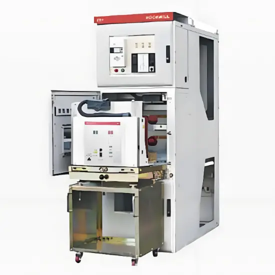
An arc flash is one of the most destructive industrial incidents you might encounter. In an instant, your switchgear can be destroyed, downstream equipment severely damaged, operations shut down for days or weeks, and personnel seriously injured or killed.
In certain facilities or applications, the potential risk of arc flash is very low; conventional (arc-flash unprotected) switchgear can be used with minimal risk. However, in most applications, it makes far more sense to rely on equipment incorporating features designed to mitigate arc flash hazards—providing a prudent "insurance policy" against the catastrophic consequences of an arc incident.
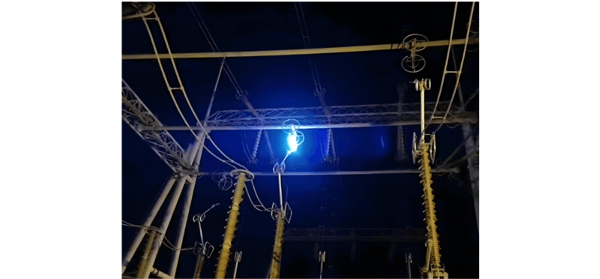
The destructive potential is immense. The energy released during an arc flash in 11kV switchgear is equivalent to the energy required to launch six space shuttles. Temperatures can reach up to 20,000°C—five times hotter than the surface of the sun—capable of vaporizing metal.
Arc faults may be rare, but they represent the most severe type of fault that can occur in a switchgear system. Potential causes are varied, including human error (the most common), technical/equipment failure, and environmental factors.
You can choose from several methods to reduce the risk of arc flash damage and injury. Three of the most common are described below.
Passive Internal Arc Protection
With passive internal arc protection, an arc fault is interrupted after it occurs by conventional protective relays. The average time between arc initiation and relay tripping ranges from 100 to 1,000 milliseconds (ms)—literally within the blink of an eye, which is typically measured at 100 to 400 ms.
Although this duration is extremely brief, the arc event will almost certainly cause sufficient damage to require switchgear repair or replacement of parts. Production processes dependent on the switchgear may also suffer severe disruption.
Switchgear with passive internal arc protection incorporates a type of ducting system that provides an "escape route" for high-pressure, high-temperature, and potentially toxic gases. Some switchgear includes a duct leading to an external area. This solution is typically used in smaller switchgear rooms. If the switchgear is located in a larger room or away from exterior walls, the ducting may vent into the room where the switchgear is installed.
Both ventilation strategies reduce or eliminate the ejection of arc gases from the front of the switchgear, helping to minimize potential injury. They also help dissipate explosive pressure, reducing internal damage to the switchgear.
Active Internal Arc Interruption
In switchgear equipped with active internal arc interruption, the protection circuit operates independently of the protective relay. The typical arc interruption time is approximately 60–80 ms, which is the sum of the time required to detect the arc, initiate the circuit breaker, and complete the breaker operation.
Sensing technology sends a signal to the upstream circuit breaker to interrupt the circuit, detecting the arc very quickly. Two common arc detection methods are current-sensing devices and/or optical light sensors that "see" the flash. The response time is faster than passive internal arc protection, but still insufficient to prevent potentially significant damage and injury.
It is well known that spring-operated circuit breakers can increase their tripping time as they age, resulting in longer arc extinguishing times. Longer tripping times are directly linked to increased arc flash damage. This is not an issue with magnetic circuit breakers, which do not slow down over time.
Active Arc Elimination
The two methods above help reduce the potential damage and injury caused by arcs, but it is important to note that both are reactive—they respond only after an arc has occurred. The third method, active arc elimination, is designed to respond so quickly that it can almost entirely eliminate the arc.
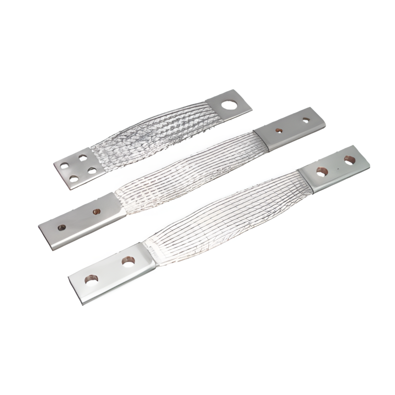
Technically, like the previous methods, it also reacts to an arc once it occurs, but its response is so rapid that damage to the switchgear is typically minimal, and the risk of injury to personnel is negligible or nonexistent. It achieves a significantly faster response—usually less than 1.5 ms and never exceeding 4 ms. Instead of tripping the upstream circuit breaker, it uses an Ultra-Fast Earthing Switch (UFES) to initiate a three-phase grounded short-circuit when an arc fault occurs.
The UFES, combined with fast and reliable fault detection via various sensing methods, helps ensure that an arc fault is extinguished almost immediately after it occurs. This results in a dramatic reduction in heat and pressure. Resetting the switchgear typically requires only wiping the interior and replacing primary switching elements—all of which can usually be completed within a few hours.
Summary
If a fire breaks out in your home, having a detection and alarm system that immediately alerts the fire department, bringing them within minutes, is reassuring. But even more reassuring would be a system that prevents the fire from starting in the first place. This is analogous to how active arc elimination distinguishes itself from other arc fault management methods.
Active arc elimination is arguably the most effective method for reducing arc flash hazards, though it comes at a slightly higher cost compared to other protection methods. For switchgear lacking any arc protection design, active arc elimination represents a relatively small investment relative to the value of the switchgear it protects. When evaluating cost-benefit, it is also important to consider additional costs arising from production or process interruptions following an arc event.
To help provide the highest level of protection for your personnel and switchgear, and to minimize the risk of operational disruption, active arc elimination via an ultra-fast earthing switch is the right choice for your switchgear.