What is Valve Type Lightning Arrester?

What is Valve Type Lightning Arrester?
Definition
A lightning arrester that comprises single or multiple gaps connected in series with a current - controlling element is referred to as a lightning arrester. The gap between the electrodes blocks the flow of current through the arrester, except when the voltage across the gap exceeds the critical gap flashover voltage. The valve - type arrester is also called a gap surge diverter or a silicon - carbide surge diverter with a series gap.
Construction of Valve - Type Lightning Arrester
The valve - type lightning arrester is constructed with a multiple - spark - gap assembly connected in series with a resistor made of a non - linear element. Each spark gap consists of two elements. To address the non - uniform voltage distribution between the gaps, non - linear resistors are connected in parallel across each individual gap. This construction helps in ensuring the proper functioning of the arrester under different electrical conditions, allowing it to effectively protect electrical equipment from lightning - induced over - voltages.

The resistor elements are fabricated from silicon carbide combined with inorganic binders. The entire assembly is encased within a sealed porcelain housing that is filled with either nitrogen gas or SF6 gas. This gas - filled environment helps to enhance the electrical insulation and performance of the arrester.
Working of Valve - Type Lightning Arrester
Under normal low - voltage conditions, the parallel resistors prevent spark - over across the gaps. As a result, slow changes in the applied voltage do not pose a threat to the electrical system. However, when rapid voltage changes occur across the terminals of the arrester, such as those induced by lightning strikes or electrical surges, the air gaps in the arrester experience spark - over. The resulting current is then discharged to the ground through the non - linear resistor. Significantly, the non - linear resistor exhibits extremely low resistance under these high - voltage, high - current conditions, effectively shunting the excessive current away from the protected electrical equipment and safeguarding it from potential damage.

After the passage of the surge, the voltage impressed across the arrester drops. Concurrently, the resistance of the arrester increases steadily until the normal operating voltage is restored. Once the surge has dissipated, a small current at the low - power frequency begins to flow through the path created by the previous flash - over. This particular current is referred to as the power follow current.
The magnitude of the power follow current gradually decreases to a value that can be interrupted by the spark gap as the gap recovers its dielectric strength. The power follow current is extinguished at the first zero - crossing of the current waveform. As a result, the power supply remains uninterrupted, and the arrester is once again ready for normal operation. This process is known as the resealing of the lightning arrester.
Stages of Valve - Type Lightning Arrester Operation
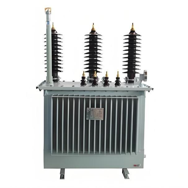
When a surge reaches the transformer, it encounters the lightning arrester, as depicted in the figure below. In approximately 0.25 μs, the voltage reaches the breakdown value of the series gap, triggering the arrester to discharge. This discharge action diverts the excessive current associated with the surge, protecting the transformer and other connected electrical equipment from potential damage caused by the high - voltage transient.

As the surge voltage rises, the resistance of the non - linear element decreases. This drop in resistance enables the continued discharge of additional surge energy. Consequently, the voltage transmitted to the terminal equipment is limited, as clearly shown in the figure below. This mechanism plays a crucial role in safeguarding the terminal equipment from the harmful effects of high - voltage surges by effectively controlling the amount of voltage reaching it.


As the voltage decreases, the current flowing to the ground diminishes simultaneously, while the resistance of the lightning arrester increases. Eventually, the lightning arrester reaches a stage where the spark gap interrupts the current flow, and the arrester effectively reseals itself. This process ensures that once the surge event subsides, the arrester returns to its normal, non - conducting state, ready to protect the electrical system from future surges.

The maximum voltage that develops across the arrester terminal and is transmitted to the terminal equipment is termed the discharge value of the arrester. This value is crucial as it determines the extent to which the arrester can safeguard the connected equipment from excessive voltage surges.
Types of Valve - Type Lightning Arresters
Valve - type lightning arresters can be classified into several types, namely station types, line types, arresters for the protection of rotating machines (distribution type or secondary type).
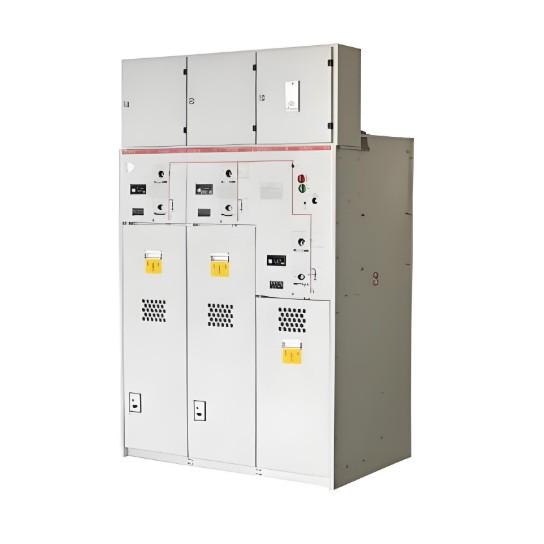
Station - Type Valve Lightning Arrester
This type of arrester is primarily used to protect critical power equipment in circuits ranging from 2.2 kV to 400 kV and even higher voltage levels. It is characterized by its high energy - dissipation capacity. This enables it to handle large amounts of surge energy, ensuring the safety of the essential power components within the station.
Line - Type Lightning Arrester
Line - type arresters are utilized for the protection of substation equipment. They have a smaller cross - sectional area, are lighter in weight, and are more cost - effective compared to station - type arresters. However, they allow a higher surge voltage across their terminals in comparison to station - type arresters and possess a lower surge - carrying capacity. Despite these differences, they are well - suited for protecting substation equipment due to their specific design and cost - efficiency.
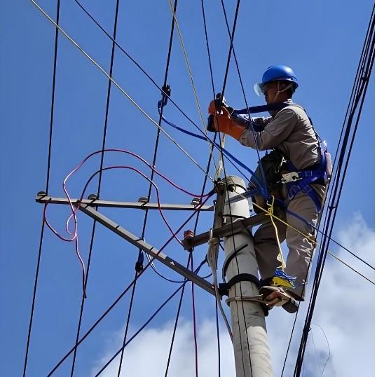
Distribution Arrester
Distribution arresters are typically mounted on poles and are employed to protect generators and motors within the distribution network. Their placement on poles makes them easily accessible for installation and maintenance while effectively safeguarding the electrical machinery in the distribution system.
Secondary Arrester
Secondary arresters are designed to protect low - voltage apparatus. Similarly, arresters for the protection of rotating machines are specifically engineered to shield generators and motors. These arresters play a vital role in ensuring the reliable operation of low - voltage and rotating equipment by preventing damage caused by voltage surges.