The two main types of instrument transformers in a power system.

I. Voltage Transformer (VT)
Voltage Transformer (Potential Transformer, abbreviated as PT; Voltage Transformer, abbreviated as VT) is an electrical device used to transform voltage levels in power circuits.
1. Operating Principle
The voltage transformer operates on the principle of electromagnetic induction and has a structure similar to that of a conventional transformer, consisting primarily of a primary winding, a secondary winding, and a core. The primary winding is connected in parallel to the high-voltage circuit being measured and has a large number of turns.
The secondary winding, with fewer turns, is connected to measuring instruments, protective relays, and other loads. Under normal operating conditions, the secondary side is approximately in an open-circuit state. According to the law of electromagnetic induction, the ratio of primary to secondary voltage is equal to the turns ratio (U₁/U₂ = N₁/N₂). This allows the high voltage to be proportionally stepped down to a standardized low voltage (typically 100V or 100/√3 V), making it safe and suitable for measurement and protection devices.
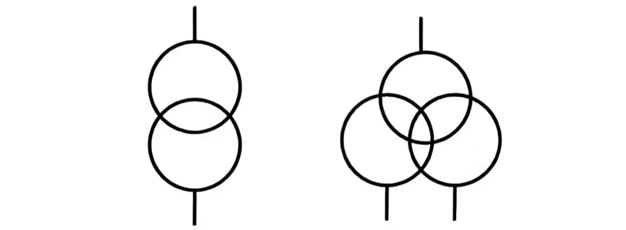
Its electrical symbol is as follows:
2. Functions
- Voltage Measurement: Steps down high system voltages to standardized low voltages (e.g., 100V or 100/√3 V) for use by voltmeters, energy meters, and other measuring instruments, enabling real-time monitoring of power system voltage.
- Relay Protection: Provides reliable voltage signals to protective relays for overvoltage, undervoltage, and other protection functions. When abnormal voltage conditions occur, the protection system responds quickly, triggering a trip command to isolate the faulty circuit and ensure system and equipment safety.
- Energy Metering and Billing: Works in conjunction with energy meters to accurately measure power consumption in high-voltage circuits. It serves as a critical basis for utility billing and energy settlement.
3. Characteristics
- High Accuracy: Measurement-grade voltage transformers have high accuracy classes (e.g., 0.2, 0.5) to ensure precise voltage measurement and energy metering. Protection-grade VTs prioritize fast response and have relatively lower accuracy classes (e.g., 3P, 6P).
- High Insulation Requirements: High-voltage VTs must withstand high operating voltages and typically use oil-immersed, SF₆ gas, or solid resin insulation for stable and reliable performance. Low-voltage VTs are mostly dry-type, with simple structure and easy maintenance.
- Secondary Side Must Not Be Short-Circuited: A short circuit on the secondary side can generate extremely high currents, potentially overheating and destroying the windings. Therefore, the secondary circuit must be protected by fuses or miniature circuit breakers.
4. Application Scenarios
- High-Voltage Applications: Suitable for transmission lines and substations with voltages of 1 kV and above (e.g., 10 kV, 35 kV, 110 kV systems). Used to monitor busbar or line voltages and provide input to protection systems, ensuring safe and stable grid operation.
- Low-Voltage Applications: Applicable to distribution systems below 1 kV (e.g., 220V residential circuits, 380V industrial systems). Commonly installed in low-voltage switchgear for monitoring consumer-side voltage or interfacing with energy meters for power measurement.
II. Current Transformer (CT)
A current transformer (CT), also known as a current transducer, is an instrument transformer that, under normal operating conditions, produces a secondary current substantially proportional to the primary current, with a phase difference approaching zero when correctly connected.
1. Operating Principle
The current transformer operates on the principle of electromagnetic induction and has a structure similar to that of a conventional transformer, consisting of a primary winding, a secondary winding, and a magnetic core. The primary winding is connected in series with the circuit being measured and has very few turns (sometimes only one turn), carrying the high primary current.
The secondary winding, with many more turns, is connected in series to measuring instruments, protective relays, and other loads, forming a closed loop. Under normal operation, the secondary side is approximately in a short-circuit condition. According to electromagnetic induction, the ratio of primary to secondary current is inversely proportional to the turns ratio (I₁/I₂ = N₂/N₁). This allows large currents to be scaled down proportionally to standardized low-level currents (typically 5A or 1A), facilitating measurement, monitoring, and protection.
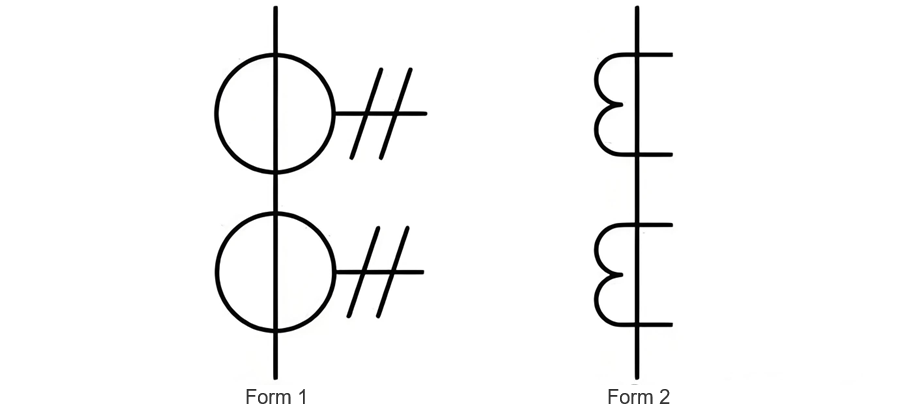
Its electrical symbol is as follows:
The ratio of the primary to secondary rated current of a current transformer is called the current transformation ratio (Ke). The expression for the current transformation ratio is:
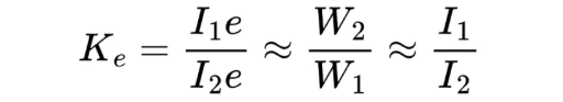
Note:
- W₁, W₂ are the number of turns in the primary and secondary windings of the transformer, respectively;
- I₁ₑ, I₂ₑ are the rated currents of the primary and secondary windings, respectively;
- I₁, I₂ are the actual currents in the primary and secondary windings, respectively.
2. Functions
- Current Measurement: Steps down high primary currents to standardized low secondary currents (e.g., 5A or 1A), enabling ammeters, energy meters, and other instruments to monitor load current in real time.
- Relay Protection: Supplies current signals to protective relays for overcurrent, differential, and distance protection. When faults such as short circuits or overloads occur, the protection system triggers a trip signal to disconnect the power supply, preventing equipment damage and system instability.
- Electrical Isolation: Provides galvanic isolation between the high-voltage/high-current primary circuit and the low-voltage secondary circuits used for measurement, control, and protection. This ensures the safety of personnel and secondary equipment.
3. Characteristics
- High Reliability: Must withstand high mechanical and thermal stresses during short-circuit events. CTs are designed with excellent dynamic and thermal stability to remain intact under extreme fault conditions.
- Multiple Winding Design: High-voltage CTs often have multiple secondary windings—one for metering (high accuracy, e.g., class 0.5) and another for protection (wide range and fast response, e.g., class 5P or 10P). Low-voltage CTs typically have single or dual windings to meet basic application needs.
- Secondary Side Must Not Be Open-Circuited: An open circuit on the secondary side can induce extremely high voltages (up to several kV) across the winding, posing serious risks of insulation breakdown, equipment damage, and electric shock. Therefore, the secondary circuit must remain closed during operation—opening it is strictly prohibited.
4. Application Scenarios
- High-Voltage Applications: Used in transmission lines and substations with voltages of 1 kV and above (e.g., 10 kV, 35 kV, 110 kV systems). Widely applied in current monitoring and protection of critical equipment such as transformers, circuit breakers, and busbars, playing a vital role in ensuring grid reliability and safety.
- Low-Voltage Applications: Applied in distribution systems below 1 kV (e.g., industrial workshops, commercial buildings, residential complexes). Typically installed in low-voltage switchboards or distribution panels for branch circuit monitoring, energy metering, or integration with residual current devices (RCDs) and smart meters to enable safe and efficient power usage management.


