• Product
  • Suppliers
  • Manufacturers
  • Solutions
  • Free tools
  • Knowledges
  • Experts
  • Communities
Search


Vacuum Tube Voltmeter (VTVM)

Encyclopedia
Encyclopedia
Field: Encyclopedia
0
China

Definition and Overview of Vacuum Tube Voltmeter (VTM)

A Vacuum Tube Voltmeter (VTM) is defined as a type of voltmeter that utilizes vacuum tubes to amplify the alternating current (AC) and direct current (DC) voltages being measured. The incorporation of vacuum tubes significantly enhances the voltmeter's sensitivity, enabling it to detect extremely weak electrical signals with remarkable precision.

Electronic voltmeters, including the VTM, are versatile instruments used for measuring various aspects of electrical voltage, such as direct voltage, root - mean - square (RMS) voltage, and peak voltage within an electrical system. Vacuum tubes offer several distinct advantages, including high input impedance, a wide frequency range, and exceptional sensitivity.

One of the most notable benefits of the VTM is its minimal current draw compared to other types of meters. In a VTM, the measuring signal is directly fed into the vacuum tube of the device. The vacuum tube then amplifies the signal and passes it on to the deflecting meter, which displays the measured voltage value.

Types of Vacuum Tube Voltmeter

The Vacuum Tube Voltmeter can be categorized into the following types:

Diode Type

Peak Reading Diode Vacuum Tube Voltmeter

Single Triode

  • Balanced Triode Type

  • Rectifiers Amplifier Type

  • Amplifier Rectifier Type

  • Simple Diode Type Voltmeter

Diode Voltmeter Circuit

The circuit of a diode voltmeter typically comprises a Permanent - Magnet Moving - Coil (PMMC) meter, a load resistor, and a vacuum tube diode. The vacuum tube diode, when connected in series with a resistor, serves to boost the strength of weak electrical signals. Thanks to the presence of the vacuum tube, the overall system becomes far more sensitive than a standard voltmeter.

To ensure accurate voltage readings from the voltmeter, it is crucial that the current and voltage have a direct proportional relationship. This is achieved through the use of a series resistor, which helps to linearize the meter's response. The circuit diagram of the diode vacuum tube voltmeter is illustrated in the figure below, providing a visual representation of its component layout and operational principles.

image.png

Diode Vacuum Voltmeter Characteristics and Limitations

In a diode vacuum voltmeter, the resistance of the series resistor is significantly higher than that of the vacuum tube diode. As a result, the resistance of the tube can be effectively neglected. This setup allows for a linear relationship to be established between the voltage and current within the circuit. When the input supply is applied, it causes the pointer of the Permanent - Magnet Moving - Coil (PMMC) meter to deflect, with the position of the pointer indicating the magnitude of the measured voltage.

Key Characteristics of Diode Vacuum Voltmeter

Input Resistance: The input resistance of the voltmeter is equivalent to the value of the series resistance. Although high - voltage resistors are employed, they actually reduce the meter's sensitivity. This relationship between resistance and sensitivity is a crucial aspect of the meter's design and operation.

Frequency Range: The frequency range of the diode voltmeter is directly influenced by the value of the series resistance. A higher value of the series resistance leads to a reduction in the meter's frequency range. This inverse relationship means that adjusting the series resistance can control the range of frequencies the voltmeter can accurately measure.

Application Limitations: Due to its relatively low input resistance and restricted frequency range, the vacuum tube voltmeter finds use in only a limited number of applications. These limitations make it less suitable for scenarios that demand high - sensitivity measurements across a broad spectrum of frequencies.

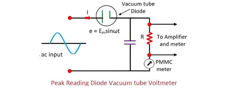
Peak Reading Diode Vacuum Tube Voltmeter

This type of voltmeter incorporates a capacitor within its circuit design. When the capacitor is connected in series with the resistance, the resulting configuration is known as the Series Type Peak Diode Reading Vacuum Voltmeter. Conversely, in the compensated shunt type voltmeter, the capacitor is connected in parallel with the series resistor. These different arrangements of the capacitor and resistor components give rise to distinct operating characteristics and measurement capabilities for each type of peak - reading voltmeter, enabling them to be applied in various electrical measurement scenarios where peak voltage determination is required.

image.png

Operation and Evolution of Peak Reading Diode Vacuum Tube Voltmeters

The operational principles of both series and shunt type peak reading diode vacuum tube voltmeters are quite similar. In operation, the capacitor within the circuit charges up to the positive peak voltage of the alternating current (AC) supply. whereafter,it discharges through the shunt resistor, causing a decrease in its voltage. The voltage is then rectified by the Permanent - Magnet Moving - Coil (PMMC) meter, which is connected in series with the resistor. Notably, the peak voltage of the input AC signal is directly proportional to the output voltage of the rectifier, enabling accurate measurement of peak values.

Historically, vacuum tube voltmeters played a significant role in electrical voltage measurement. However, with the advancement of electronics technology, they have largely been supplanted by more modern alternatives. Today, transistor voltmeters (TVM) and field - effect voltmeters (FETVM) have become the preferred choice for voltage measurement tasks. These newer instruments offer improved performance characteristics, such as higher input impedance, wider frequency response, better stability, and enhanced accuracy. They also tend to be more compact, energy - efficient, and reliable, making them better suited to the demands of contemporary electrical and electronic engineering applications.

Give a tip and encourage the author!
Recommended
 Causes and Preventive Measures of Fire and Explosion in Oil Circuit Breakers
Causes and Preventive Measures of Fire and Explosion in Oil Circuit Breakers
Causes of Fire and Explosion in Oil Circuit Breakers When the oil level in an oil circuit breaker is too low, the oil layer covering the contacts becomes too thin. Under the effect of the electric arc, the oil decomposes and releases flammable gases. These gases accumulate in the space beneath the top cover, mixing with air to form an explosive mixture, which can ignite or explode under high temperature. If the oil level inside the tank is too high, the released gases have limited space to expan
Felix Spark
11/06/2025
THD Measurement Error Standards for Power Systems
Error Tolerance of Total Harmonic Distortion (THD): A Comprehensive Analysis Based on Application Scenarios, Equipment Accuracy, and Industry StandardsThe acceptable error range for Total Harmonic Distortion (THD) must be evaluated based on specific application contexts, measurement equipment accuracy, and applicable industry standards. Below is a detailed analysis of key performance indicators in power systems, industrial equipment, and general measurement applications.1. Harmonic Error Standar
Edwiin
11/03/2025
How Vacuum Tech Replaces SF6 in Modern Ring Main Units
Ring main units (RMUs) are used in secondary power distribution, directly connecting to end-users such as residential communities, construction sites, commercial buildings, highways, etc.In a residential substation, the RMU introduces 12 kV medium voltage, which is then stepped down to 380 V low voltage through transformers. The low-voltage switchgear distributes electrical energy to various user units. For a 1250 kVA distribution transformer in a residential community, the medium-voltage ring m
James
11/03/2025
Why Monitoring Accuracy Matters in Power Quality Systems
The Critical Role of Monitoring Accuracy in Power Quality Online DevicesThe measurement accuracy of online power quality monitoring devices is the core of the power system’s “perception capability,” directly determining the safety, economy, stability, and reliability of power supply to users. Inadequate accuracy leads to misjudgment, incorrect control, and flawed decision-making—potentially causing equipment damage, economic losses, or even grid failures. Conversely, high accuracy enables precis
Oliver Watts
10/30/2025
Send inquiry
Download
Get the IEE Business Application
Use the IEE-Business app to find equipment, obtain solutions, connect with experts, and participate in industry collaboration anytime, anywhere—fully supporting the development of your power projects and business.