Power Plant Fire Protection System

03/20/2024

WechatIMG1822.jpeg

With the advent of industrialization the demand for power is also on the surge like never before. But augmenting without giving the due consideration for Fire protection and detection system would be detrimental and should not be done.
Thermal Power Plants are classified under the ordinary Hazard Occupancy as per Tariff Advisory Committee (TAC) of India. The design and installation of complete fire protection system shall comply with the regulations of TAC. In the absence of TAC regulations, the National Fire Protection Association (NFPA) standard shall be adopted. The system should be designed in such a manner that it is acceptable to approving statutory body (like TAC) for insurance companies of India and enable an owner to obtain the maximum rebate on its insurance premium.

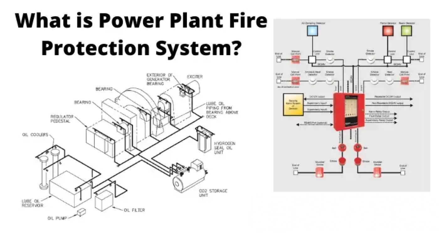
Thermal Power Plants are characterized by their complex overall system made of a range of different operating modules. In addition to these conditions such as extremely hot surfaces, lubricating oils and coal and coal dust pose huge fire risks. Elements of Fire Protection System is covered in this Portion of Part-I.
This section comprises of following which broadly are the elements of the fire protection system:

Fire Water Reservoir or Fire water Pump House

Water pump house plays an important role in fire protection system, so the complete fire pump arrangement shall be in line with the requirements of TAC. Water storage tank is required for storage of water and water will be drawn as and when required for fire protection. All the fire pumps should work automatically by use of Pressure switches; however stopping of all the fire pumps shall be manual only.
The possible sources of supply of water to storage tank will be from two different sources:

  • From raw water pump discharge header.

  • From CW blow down the system.

The fire water storage tank shall be provided with two equal compartments and both the compartments shall be interconnected through separate isolation valve and each compartment shall be connected to a common suction header of fire water pumps so that any fire pump can be fed by either fire water storage compartment as per TAC regulations.
At least two (2) headers shall be taken out of pump house for making loops around various risks. Each loop shall be interconnected for better reliability of the system. To isolate the system due to damage/repair, suitable nos. of gate valve should be provided.

Pumps Installed in Fire Water Pump House

Dedicated fire water pumps shall be provided for the fire hydrant and spray system. Blind flange with valve connection for future expansion shall be provided in the fire hydrant and spray system network. The installed fire water pump capacity and head shall be designed as per system requirement/TAC recommendations.

Following are the fire water pumps installed in the fire water pump house:

  1. Electric motor driven main fire water pump.

  2. Diesel engine driven pumps

  3. All diesel engine driven pumps shall be provided with 2 × 100% battery chargers and batteries.

  4. Electric motor driven fire water jockey pumps (one working and one stand by).

  5. Air compressor for pressurizing hydro-pneumatic tank.

Fire Water Pumps Data Sheet

For selection of rated capacity, rpm and material construction are:

1.4

TAC approval required

yes

yes

yes

1.5

Used for service like

Hydrant and spray system

Hydrant and spray system

Common for Hydrant and spray system

2.0

Material of construction


2.1

Casing

SS304

SS304

SS304

2.2

Impeller

Stainless steel

Stainless steel

Stainless steel

2.3

Shaft

Stainless steel

Stainless steel

Stainless steel


Control and operating philosophy

Fire water ring main network shall be a pressurized system provided with automatic starting of fire water pumps. The mode of operation of fire water pumping system for following shall be described in Part-II and III.

  • Hydrant and MVWSS

  • Hydrant and HVWSS

  • Fixed Foam system

  • Fire water booster pump

Constructional requirements

  • All hydrant, spray and foam system pipe mains/pipes shall be routed above ground on top of the concrete pedestals at regular intervals.

  • In main plant area and coal stock yard area pipe lines shall be routed in RCC pipe trenches filled with sand and covered with pre-cast RCC removable covers. Pipe trenches crossing through road or rail shall be through Hume pipes.

  • Fire water pipes shall be of carbon steel conforming to IS:1239 (medium grade) and IS:3589.

  • All above ground piping shall be adequately supported by concrete pedestals at regular intervals.

  • All buried pipes shall be double coated and wrapped as per IS:10221 or IS:15337.

  • The entire pipe net work shall be hydraulically designed in such manner that the velocity of water in any section does not exceed 5.0 m/sec.

  • Fire pump pressure has to be decided in such a manner that the requirement of the highest pressure at the remotest and highest hydrant can be meet at the same time in line with the TAC requirements.

  • Hose cabinet shall be provided with 16 SWG thick body and 3 mm glass. The hose shall be provided with key box and pedestal. Fire hose shall be of IS 636 type-A.

Hydrant System

(is covered in part-II)

Spray System

(is covered in part-II)

Fix Foam system

(is covered in part-III)

Potable and mobile extinguisher

(is covered in part-III)

Statement: Respect the original, good articles worth sharing, if there is infringement please contact delete.

Hello,I'm Wdwiin. A decade of hands-on experience in electrical engineering, specializing in high-voltage systems, smart grids, and renewable energy technologies. Passionate about technical exchange and knowledge sharing, committed to interpreting industry trends with professional insights to empower peers. Connection creates value—let’s explore the boundless possibilities of the electrical world together!

What is the difference between a dielectric and an insulator?
Dielectrics and insulators are distinguished primarily by their applications. One of the main differences is that a dielectric can store electrical energy by becoming polarized in an electric field, whereas an insulator resists the flow of electrons to prevent current conduction. Other key differences between them are outlined in the comparison chart below.Definition of DielectricA dielectric material is a type of insulator that contains few or no free electrons. When subjected to an electric fi
08/30/2025
What losses occur during operation of the transformer? How to reduce losses?
Transformers experience various types of losses during operation, primarily categorized into two main types: copper losses and iron losses.Copper LossesCopper losses, also known as I²R losses, are caused by the electrical resistance of the transformer windings—typically made of copper. As current flows through the windings, energy is dissipated in the form of heat. These losses are proportional to the square of the load current (I²R), meaning they increase significantly with high
Rockwell
08/29/2025
Cable Fault Detection, Testing, Location and Repair
I. Methods for Cable Testing and Inspection:Insulation Resistance Test: Use an insulation resistance tester to measure the insulation resistance value of the cable. A high insulation resistance value indicates good insulation, while a low value may suggest insulation problems requiring further investigation.Voltage Withstand Test: Apply a high-voltage test using a high-voltage tester to verify whether the cable can withstand high voltage under its rated operating conditions. Under normal circums
08/29/2025
Cable Quality Inspection and Cable Detection & Testing
Power cable quality inspection and cable testing are conducted to ensure that the cable's quality and performance meet specified requirements, thereby guaranteeing the safe and stable operation of power systems. Below are some common contents of power cable quality inspection and cable testing:Visual Inspection: Check the cable surface for physical defects such as damage, deformation, or scratches to ensure the cable's exterior is intact.Dimensional Measurement: Measure dimensional parameters su
08/29/2025
Inquiry
Download
IEE-Business is dedicated to serving the personnel in the global power industry.
Join IEE-Business, not only can you discover power equipment and power knowledge, but also canhnd like - minded friends!