What is a Standalone Solar PV System?

03/20/2024

WechatIMG1792.jpeg

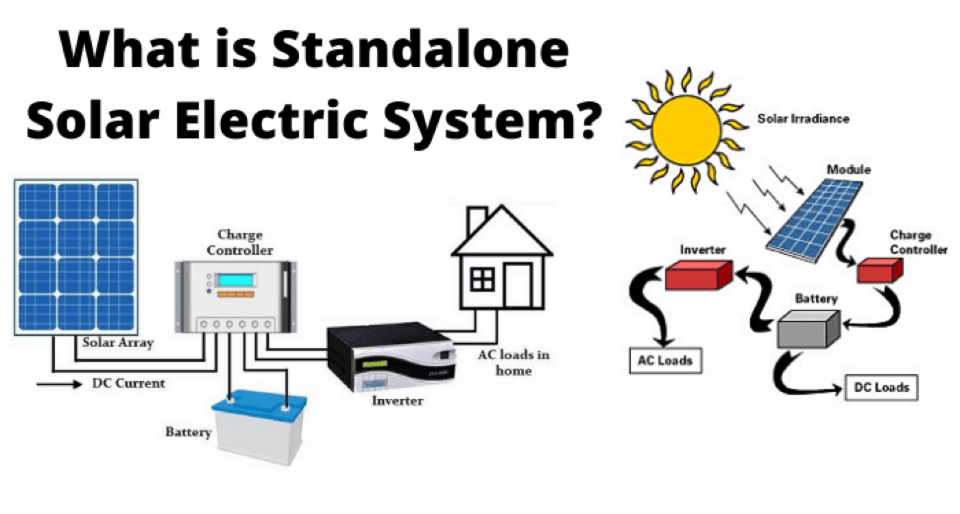
A standalone solar PV system is a system that uses solar photovoltaic (PV) modules to generate electricity from sunlight and does not rely on the utility grid or any other source of electricity. A standalone solar PV system can provide power for various applications, such as lighting, water pumping, ventilation, communication, and entertainment, in remote or off-grid locations where grid electricity is unavailable or unreliable.

A standalone solar PV system typically consists of four main components:

  • Solar PV modules or arrays that convert sunlight into direct current (DC) electricity.

  • A charge controller or a maximum power point tracker (MPPT) regulates the voltage and current from the solar PV modules to the battery and the load.

  • A battery or a battery bank that stores the excess electricity generated by the solar PV modules during the day and supplies it to the load when needed, especially at night or during cloudy weather.

  • An inverter that converts DC electricity from the battery or the solar PV modules to alternating current (AC) electricity for AC loads.

Depending on the type and size of the load, a standalone solar PV system can be configured in different ways. In this article, we will discuss four common types of standalone solar PV systems and their advantages and disadvantages.

Standalone Solar PV System with Only DC Load

This is the simplest type of standalone solar PV system, as it requires only two main components: a solar PV module or array and a DC load. The solar PV module or array is directly connected to the DC load, such as a fan, a pump, or a light, without any intermediate device. This system can only operate during daylight hours when there is enough sunlight to power the load.

The advantage of this system is its low cost and simplicity, as it does not need a battery, a charge controller, or an inverter. However, the disadvantage is its limited application and performance, as it cannot provide power at night or during low sunlight conditions. Moreover, the output voltage and current from the solar PV module or array vary depending on the intensity and angle of sunlight, which may affect the operation of the load.

Standalone Solar PV System with DC Load and Electronic Control Circuit

This type of standalone solar PV system improves upon the previous one by adding an electronic control circuit between the solar PV module or array and the DC load. The electronic control circuit can be either a charge controller or an MPPT. The charge controller regulates the voltage and current from the solar PV module or array to prevent overcharging or over-discharging of the battery (if present) and to protect the load from voltage fluctuations. The MPPT optimizes the power output from the solar PV module or array by tracking its maximum power point under different sunlight conditions.

The advantage of this system is that it enhances the utilization and efficiency of the solar PV module or array and extends its lifespan. It also improves the performance and reliability of the load by providing stable voltage and current. However, the disadvantage is that it increases the cost and complexity of the system, as it requires an additional device and wiring. Moreover, this system still cannot provide power at night or during low sunlight conditions without a battery.

Standalone Solar PV System with DC Load, Electronic Control Circuit, and Battery

This type of standalone solar PV system adds a battery or a battery bank to the previous one to enable power supply at night or during low sunlight conditions. The battery stores the excess electricity generated by the solar PV module or array during the day and supplies it to the load when needed. The electronic control circuit regulates the charging and discharging of the battery and protects it from overcharging or over-discharging.

The advantage of this system is that it can provide continuous and reliable power for both day and night applications. It can also handle variable loads and peak demands by using different sizes and types of batteries. However, the disadvantage is that it further increases the cost and complexity of the system, as it requires more components and maintenance. The battery also adds weight and volume to the system and has a limited lifespan and efficiency.

Standalone Solar PV System with AC/DC Load, Electronic Control Circuit, and Inverter

This type of standalone solar PV system adds an inverter to the previous one to enable the use of AC loads, such as appliances, computers, TVs, and lights, as well as DC loads. The inverter converts the DC electricity from the battery or the solar PV module or array to AC electricity of the desired voltage and frequency. The inverter can be either a stand-alone device or integrated with the charge controller or the MPPT.

The advantage of this system is that it can provide both AC and DC power for a wide range of applications and devices. It can also be more efficient and flexible than using separate systems for AC and DC loads. However, the disadvantage is that it further increases the cost and complexity of the system, as it requires an additional device and wiring. The inverter also adds losses and noise to the system and may need protection from surges and faults.

Conclusion

Standalone solar PV systems are useful and viable options for providing electricity in remote or off-grid locations where grid power is unavailable or unreliable. They can also be used to supplement grid power or to reduce dependence on fossil fuels. Depending on the type and size of the load, different types of standalone solar PV systems can be configured with various components, such as solar PV modules or arrays, charge controllers or MPPTs, batteries, inverters, and AC/DC loads. Each type of system has its own advantages and disadvantages in terms of cost, complexity, performance, reliability, and maintenance.

To design a suitable standalone solar PV system for a specific application, several factors need to be considered, such as:

  • The load characteristics (power, voltage, current, frequency, AC/DC)

  • The solar resource availability (sunlight hours, intensity, angle)

  • The system sizing (solar PV module or array size, battery capacity, inverter rating)

  • The system configuration (series or parallel connection of modules or batteries)

  • The system protection (fuses, breakers, surge protectors)

  • The system monitoring (meters, indicators, sensors)

Statement: Respect the original, good articles worth sharing, if there is infringement please contact delete.

Hello,I'm Wdwiin. A decade of hands-on experience in electrical engineering, specializing in high-voltage systems, smart grids, and renewable energy technologies. Passionate about technical exchange and knowledge sharing, committed to interpreting industry trends with professional insights to empower peers. Connection creates value—let’s explore the boundless possibilities of the electrical world together!

What is the difference between a dielectric and an insulator?
Dielectrics and insulators are distinguished primarily by their applications. One of the main differences is that a dielectric can store electrical energy by becoming polarized in an electric field, whereas an insulator resists the flow of electrons to prevent current conduction. Other key differences between them are outlined in the comparison chart below.Definition of DielectricA dielectric material is a type of insulator that contains few or no free electrons. When subjected to an electric fi
08/30/2025
What losses occur during operation of the transformer? How to reduce losses?
Transformers experience various types of losses during operation, primarily categorized into two main types: copper losses and iron losses.Copper LossesCopper losses, also known as I²R losses, are caused by the electrical resistance of the transformer windings—typically made of copper. As current flows through the windings, energy is dissipated in the form of heat. These losses are proportional to the square of the load current (I²R), meaning they increase significantly with high
Rockwell
08/29/2025
Cable Fault Detection, Testing, Location and Repair
I. Methods for Cable Testing and Inspection:Insulation Resistance Test: Use an insulation resistance tester to measure the insulation resistance value of the cable. A high insulation resistance value indicates good insulation, while a low value may suggest insulation problems requiring further investigation.Voltage Withstand Test: Apply a high-voltage test using a high-voltage tester to verify whether the cable can withstand high voltage under its rated operating conditions. Under normal circums
08/29/2025
Cable Quality Inspection and Cable Detection & Testing
Power cable quality inspection and cable testing are conducted to ensure that the cable's quality and performance meet specified requirements, thereby guaranteeing the safe and stable operation of power systems. Below are some common contents of power cable quality inspection and cable testing:Visual Inspection: Check the cable surface for physical defects such as damage, deformation, or scratches to ensure the cable's exterior is intact.Dimensional Measurement: Measure dimensional parameters su
08/29/2025
Inquiry
Download
IEE-Business is dedicated to serving the personnel in the global power industry.
Join IEE-Business, not only can you discover power equipment and power knowledge, but also canhnd like - minded friends!