

Aikin da ya yi da zan iya ya kula da abubuwa da ke kan kuli da tsawon voltage da amfani da muhimmanci na aiki da zan iya. Amma aikin da ya yi da zan iya ana iya aiki a matsayin voltmeter. Idan yana ba da wata tambayar a cikin kokarin da muke: ba ni da dalilin da ake amfani da aikin da ya yi da zan iya a fadin gida idan an samun wasu wadanda suka da AC voltmeters masu suna daban-daban kamar electrodynamometer type instruments, thermocouple type instruments, etc? Amsa a wannan tambayar ta ce mai kyau da kuma an ambaci a haka.
Gaskiya da cost of electrodynamometer type of instruments ya fi girma da aikin da ya yi da zan iya. Amma aikin da ya yi da zan iya ta fi shahara da electrodynamometer type of instruments. Saboda haka, aikin da ya yi da zan iya ana da darasi a kan electrodynamometer type instruments.
Thermocouple instruments suka fi karfi da aikin da ya yi da zan iya. Amma thermocouple type of instruments ana amfani da su a wurare da tsari da suka fi karfi.
Idan ba a tafi da aiki da zan iya, aikin da ya yi da zan iya, yana bukatar da a tafi da cewa da current characteristics of ideal and practical rectifier element called diode.
Barazan da a nan za a tafi da ideal characteristics of rectifying element. Me kuke so kuwa ce ideal rectifying element? Rectifying element ce wani wanda ya ba da zero resistance idan ya yi forward biased da kuma ya ba da infinite resistance idan ya yi reversed biased.
Ana amfani da wannan property don rectify the voltages (rectification means to convert an alternating quantity into direct quantity i.e. AC to DC). Za a duba diagrammin circuit da aka bayar.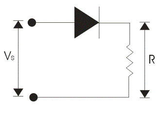
A cikin diagrammin circuit da aka bayar, an haɗa ideal diode a series da voltage source da kuma load resistance. Idan muna yi forward biased diode, yana yi shiga da zero electrical resistance path. Don haka, yana yi shiga da short circuited. Muna iya yi forward biased diode ta hanyar haɗa positive terminal of the battery with anode da kuma negative terminal with cathode. The forward characteristic of rectifying element or diode is shown in the voltage current characteristic.
Idan muna yi reverse biased, yana ba da infinite electrical resistance da kuma yana yi shiga da open circuit. The complete voltage current characteristics are shown below.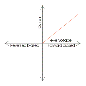
Za a duba circuit da same, amma farko ce na a nan ake amfani da practical rectifying element instead of ideal one. Practical rectifying element ana da some finite forward blocking voltage and high reverse blocking voltage. Muna iya yi same procedure don obtain the voltage current characteristics of practical rectifying element. Idan muna yi practical rectifying element forward biased, ba yake yi shiga har zuwa applied voltage is not greater than the forward breakdown voltage or we can say knee voltage. Idan applied voltage becomes greater than the knee voltage, diode or rectifying element will come under conduction mode. Don haka, yana yi shiga da short circuited but due to some electrical resistance there is voltage drop across this practical diode. Muna iya yi practical rectifying element forward biased ta hanyar haɗa positive terminal of the battery with anode da kuma negative terminal with cathode. The forward characteristic of practical rectifying element or diode is shown in the voltage current characteristic. Idan muna apply negative voltage, yana ba da finite resistance and the negative voltage till the applied voltage becomes equal to reverse break down voltage and thus it behaves as open circuit. The complete characteristics are shown below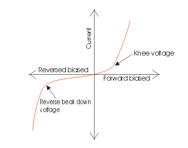
Aikin da ya yi da zan iya ana amfani da two types of rectifier circuits:
Za a duba half wave rectifier circuit da aka bayar, a nan an haɗa rectifying element a series da sinusoidal voltage source, permanent magnet moving coil instrument da kuma multiplier resistor.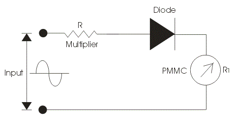
The function of this multiplier electrical resistance is to limit the current drawn by the permanent magnet moving coil type of instrument. It is very essential to limit the current drawn by the permanent magnet moving coil instrument because if the current exceeds the current rating of PMMC then it destructs the instrument. Now here we divide our operation in two parts. In first part we apply constant DC voltage to the above circuit. In the circuit diagram we are assuming the rectifying element as ideal one.
Let us mark the resistance of multiplier be R, and that of permanent magnet moving coil instrument be R1. The DC voltage produces a full scale deflection of magnitude I=V/(R+R1) where V is root mean square value of voltage. Now let us consider second case, in this case we will apply AC sinusoidal AC voltage to the circuit v =Vm × sin(wt) and we will get the output waveform as shown. In the positive half cycle the rectifying element will conduct and in the negative half cycle it does not conduct. So we will get a pulse of voltage at moving coil instrument which produces pulsating current thus pulsating current will produce pulsating torque.
The deflection produced will correspond to the average value of voltage. So let us calculate the average value of electric current, in order to calculate the average value of voltage we have to integrate the instantaneous expression of the voltage from 0 to 2 pi. So the calculated average value of voltage comes out to be 0.45V. Again we have V is root mean square value of current. Thus we conclude that the sensitivity of the ac input is 0.45 times the sensitivity of DC input in case of half wave rectifier.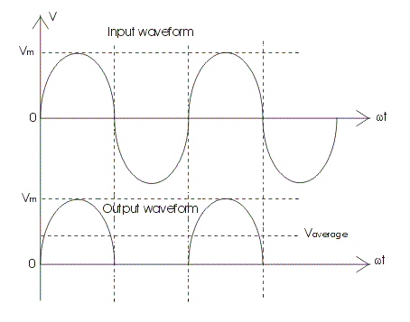
Let us consider a full wave rectifier circuit given below.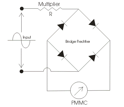
We have used here a bridge rectifier circuit as shown. Again we divide our operation into two parts. In the first we analyze the output by applying the DC voltage and in another we will apply AC voltage to the circuit. A series multiplier resistance is connected in series with the voltage source which has the same function as described above. Let us consider first case here we applying DC voltage source to the circuit. Now the value of full scale deflection current in this case is again V/(R+R1), where V is the root mean square value of the applied voltage, R is the resistance of the resistance multiplier and R1 which is the electrical resistance of the instrument. The R and R1 are marked in the circuit diagram. Now let us consider second case, in this case we will apply AC sinusoidal voltage to the circuit which is given v = Vmsin(wt) where Vm is the peak value of the applied voltage again if we calculate the value of full scale deflection current in this case by applying the similar procedure then we will get an expression of full scale current as .9V/(R+R1). Remember in order to obtain the average value of voltage we should integrate the instantaneous expression of voltage from zero to pi. Thus comparing it DC output we conclude that the sensitivity with AC input voltage source is 0.9 times the as in the case of DC input voltage source.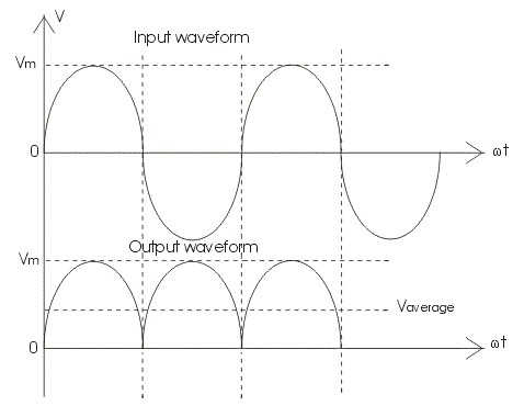
The output wave is shown below. Now we are going to discuss the factors which affect the performance of Rectifier type instruments:
Rectifier type of instruments is calibrated in terms of root mean square values of sinusoidal wave of voltages and current. The problem is that the input waveform may or may not have same form factor on which the scale of these meter is calibrated.
There may be some error due to the rectifier circuit as we not included the resistance of the rectifier bridge circuits in both the case. The non linear characteristics of bridge may distort the current and voltage waveform.
There may variation in the temperature due to which the electrical resistance of the bridge changes hence in order to compensate this kind of errors we should apply multiplier resistor with high temperature coefficient.
Effect of capacitance of the bridge rectifier: Bridge rectifier has imperfect capacitance thus due to this it byp asses the high frequency currents. Hence there is decrement in the reading.
The sensitivity of Rectifier type instruments is low in case of AC input voltage.
Following are the advantages of the rectifier type of instruments:
The accuracy of rectifier type instrument is about 5 percent under normal operating condition.
The frequency range of operation can be extended to high value.
They have uniform scale on the meter.
They have low operating value of current and voltages.
The loading effect of an AC rectifier voltmeter in both the cases (i.e. half wave diode rectifier and full wave diode rectifier) is high as compared to the loading effects of DC voltmeters as the sensitivity of the voltmeter either using in half wave or full wave rectification is less than the sensitivity of DC voltmeters.
Statement: Respect the original, good articles worth sharing, if there is infringement please contact delete.


