Analysis of Earth Fault Protection in Low-Voltage Distribution Systems for Data Centers

08/25/2025

Low-voltage power distribution lines are widely used across various industries, and the distribution environments are complex and diverse. These lines are accessed not only by professionals but also frequently by non-specialists, significantly increasing the risk of faults. Improper design or installation can easily lead to electric shock (particularly indirect contact), damage to wiring, or even electrical fires.

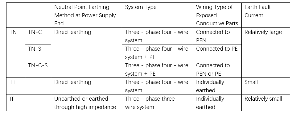
The grounding system is a critical component of low-voltage distribution networks—a technically complex and safety-critical engineering element. The type of grounding system is closely linked to the effectiveness of grounding fault protection.

Currently, the low-voltage distribution systems in data centers across China primarily adopt the TN-S grounding configuration. These systems involve numerous low-voltage distribution devices and extensive cabling, representing substantial capital investment. Any fault, if not promptly addressed, could result in severe personnel injuries and significant property damage, hence demanding extremely high reliability from the distribution system.

To provide a more comprehensive and systematic explanation of grounding fault protection in low-voltage distribution systems, the following section presents a comparative analysis of various grounding configurations and their corresponding fault protection methods.

General Requirements for Earth Fault Protection

  • The earth fault protection system shall be designed to effectively prevent indirect electric shock to personnel, as well as accidents such as electrical fires and damage to wiring.
  • Exposed conductive parts of electrical equipment shall be reliably connected to the protective conductor (PE conductor) in accordance with the specific conditions of the system. Externally accessible conductive parts that may be simultaneously touched shall be connected to the same grounding system to ensure potential equalization.
  • Where the earth fault protection of an electrical installation cannot meet the requirement for automatic disconnection of the fault circuit within the specified time, supplementary equipotential bonding shall be implemented within the local area to reduce touch voltage and enhance safety.

Earth Fault Protection in TN Systems

In TN systems, the operating characteristics of earth fault protection for distribution circuits shall satisfy the following condition:

Zs × Ia ≤ Uo

Where:

  • Zs — Total impedance of the earth fault loop (Ω);
  • Ia — Current required to cause the protective device to automatically disconnect the fault circuit within the specified time (A);
  • Uo — Nominal voltage between phase and earth (V).

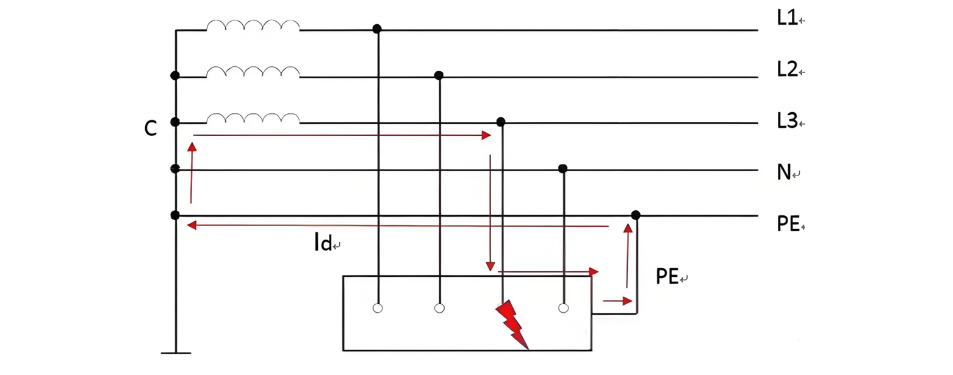
As illustrated in the figure below, when a ground fault occurs on phase L3, the fault current (Id) flows through the L3 phase conductor, the metallic enclosure of the equipment, and the PE protective conductor, forming a closed loop. Zs represents the total impedance of the phase-to-protective conductor loop, and Uo is 220V.

Disconnection Time Requirements for Earth Fault Protection in TN Systems

For TN system distribution circuits with a nominal phase-to-earth voltage of 220V, the time required for earth fault protection to disconnect the fault circuit shall comply with the following requirements:

  • For distribution circuits or final circuits supplying fixed electrical equipment, the disconnection time should not exceed 5 seconds;
  • For circuits supplying hand-held or mobile equipment, or socket-outlet circuits, the disconnection time shall not exceed 0.4 seconds.

Selection of Earth Fault Protection Methods in TN Systems:

a. When the above disconnection time requirements can be met, overcurrent protection may be used to also serve as earth fault protection;
b. When overcurrent protection cannot meet the requirements, but zero-sequence current protection can, zero-sequence current protection shall be used. The protection setting value should be greater than the maximum unbalanced current under normal operating conditions;
c. When neither of the above methods can satisfy the requirements, residual current operated protection (RCD, or "leakage current protection") shall be employed.

Earth Fault Protection in TT Systems

The operating characteristic of earth fault protection in TT system distribution circuits shall satisfy the following condition:

RA × Ia ≤ 50 V

Where:

  • RA — The sum of the earth electrode resistance of exposed conductive parts and the neutral (N) conductor earth resistance (Ω);
  • Ia — The current required to ensure the protective device reliably disconnects the fault circuit (A).

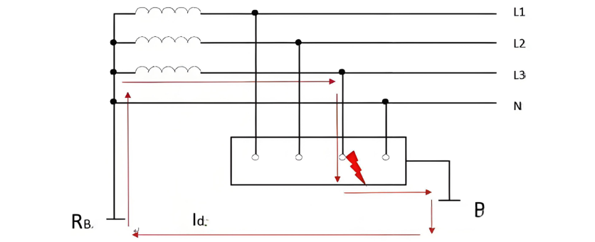
As shown in the figure below, when a ground fault occurs on phase L3, the fault current (Id) flows through the L3 conductor, the metallic enclosure of the equipment, the equipment's grounding electrode resistance, the earth, and back to the source via the neutral point grounding resistance, forming the fault loop. The value of 50 V represents the safety limit for touch voltage, ensuring that the voltage to which a person may be exposed during a fault does not pose a danger.

Selection of Earth Fault Protection for TT Systems:

  • When overcurrent protective devices are used, the current Ia shall be the value that ensures disconnection of the fault circuit within 5 seconds;
  • When instantaneous-trip overcurrent protective devices are used, Ia shall be the minimum current required to ensure instantaneous operation;
  • When residual current operated protective devices (RCDs, or "leakage current protection") are used, Ia shall be taken as their rated residual operating current In.

Earth Fault Protection in IT Systems

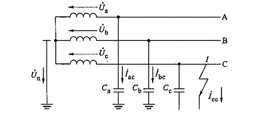
Under normal operation, the leakage current in each phase of an IT system consists of capacitive current to earth—denoted as Iac, Ibc, Ica—and the vector sum of these three-phase earth capacitance currents is zero. Therefore, the neutral point voltage can be considered as 0V.

When the first earth fault occurs, the voltage-to-earth on the healthy (non-faulted) phases increases by a factor of √3. This indicates that IT systems impose higher insulation level requirements on electrical equipment compared to TN and TT systems. However, since the current during the first earth fault is very small (primarily capacitive current), the system can continue to operate. Nevertheless, an insulation monitoring device must be installed to provide an alarm upon detection of the first fault, enabling operation and maintenance personnel to locate and rectify the fault promptly.

  • When exposed conductive parts are individually earthed, the disconnection of the fault circuit during a second fault on a different phase shall comply with the earth fault protection requirements of the TT system;
  • When exposed conductive parts are connected to a common earthing system, the disconnection of the fault circuit during a second fault on a different phase shall comply with the earth fault protection requirements of the TN system;
  • The IT system should not have a neutral conductor (N line) derived.

In summary, different power supply earthing systems exhibit distinct earth fault characteristics. Only by fully understanding the fault behavior of each system can an appropriate and compatible earth fault protection scheme be designed, ensuring safe and reliable operation of power supply and utilization systems.

Hello! I'm Leon, with 20 years of extensive experience in the power industry. My expertise spans from power distribution equipment to grid operations and maintenance, grounded in robust hands-on and theoretical knowledge. Currently, I focus on sharing insights into electrical equipment fault diagnosis, demystifying complex technical challenges through accessible explanations. I welcome collaboration with industry peers and enthusiasts to collectively explore the intricacies of the power sector.

What is the difference between a dielectric and an insulator?
Dielectrics and insulators are distinguished primarily by their applications. One of the main differences is that a dielectric can store electrical energy by becoming polarized in an electric field, whereas an insulator resists the flow of electrons to prevent current conduction. Other key differences between them are outlined in the comparison chart below.Definition of DielectricA dielectric material is a type of insulator that contains few or no free electrons. When subjected to an electric fi
08/30/2025
Fault Analysis and Treatment of Oil-Immersed Transformers
Oil Leakage at Welded JointsOil leakage at welded joints primarily stems from poor welding quality, such as incomplete or detached welds, and defects like pinholes and gas pores. Although oil-immersed transformers are initially coated with solder and paint during manufacturing, potentially masking these issues temporarily, the defects tend to surface during operation. Additionally, electromagnetic vibration can cause weld cracks, leading to oil leakage.To resolve such leaks, the first critical s
08/29/2025
What losses occur during operation of the transformer? How to reduce losses?
Transformers experience various types of losses during operation, primarily categorized into two main types: copper losses and iron losses.Copper LossesCopper losses, also known as I²R losses, are caused by the electrical resistance of the transformer windings—typically made of copper. As current flows through the windings, energy is dissipated in the form of heat. These losses are proportional to the square of the load current (I²R), meaning they increase significantly with high
Rockwell
08/29/2025
Cable Fault Detection, Testing, Location and Repair
I. Methods for Cable Testing and Inspection:Insulation Resistance Test: Use an insulation resistance tester to measure the insulation resistance value of the cable. A high insulation resistance value indicates good insulation, while a low value may suggest insulation problems requiring further investigation.Voltage Withstand Test: Apply a high-voltage test using a high-voltage tester to verify whether the cable can withstand high voltage under its rated operating conditions. Under normal circums
08/29/2025
Inquiry
Download
IEE-Business is dedicated to serving the personnel in the global power industry.
Join IEE-Business, not only can you discover power equipment and power knowledge, but also canhnd like - minded friends!