IEC61850 model for GIS with Non Conventional Instrument Transformers (NCIT)

05/06/2025

IEC 61850 Standards and NCIT - Related Communication in GIS
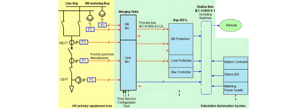
The IEC 61850 8 - 1 standard is specifically applicable to station bus communication, providing a framework for data exchange and interoperability within substation automation systems. On the other hand, the IEC 61850 9 - 2 LE standard is directly relevant to the communication of Non - Contact Inductive Transducer (NCIT) sensors.
Ethernet optical communication drivers play a crucial role in this setup. Their significance stems from the utilization of glass core fiber optics as the physical transmission medium. Fiber optics offer advantages such as high - speed data transfer, immunity to electromagnetic interference, and long - distance communication capabilities, making these drivers essential for reliable and efficient communication.
Due to the inherently low - level output signals from an NCIT metering element, the presence of a "Primary Converter" (PC) in close proximity is indispensable. The PC is an electronic device equipped with several key functions. It incorporates signal filtering through a low - pass filter to eliminate unwanted high - frequency noise, digitizes the signal using a Controller Area Network (CAN) interface, and performs necessary signal processing. These operations ensure that the raw signals from the NCIT are in a suitable form for further transmission and analysis.
The computational capabilities of the PC are harnessed to communicate with a device known as the Merging Unit (MU) via a proprietary protocol. The MU serves as a central hub, aggregating inputs from multiple PCs. It is equipped with multiple output ports, which are designed to enable communication with various pieces of equipment, including protection relays, bay controllers, and metering devices. By distributing the processed measurements to these different systems, the MU facilitates seamless integration and coordinated operation within the overall electrical infrastructure.
To achieve optimal metering accuracy, it is imperative to match the sensitivity level of the metering element with the background noise level of the printed circuit board. Minimizing the background noise to the lowest possible level ensures that the metering element can accurately detect and measure electrical quantities without being affected by spurious signals.
Figure [1] illustrates the IEC 61850 communication protocol in conjunction with NCIT sensors for Gas Insulated Substations (GIS). This visual representation provides a comprehensive overview of how the various components interact and communicate, highlighting the integration of standards - based communication and specialized sensor technology to enhance the performance, reliability, and efficiency of GIS - based electrical systems.

Hello,I'm Wdwiin. A decade of hands-on experience in electrical engineering, specializing in high-voltage systems, smart grids, and renewable energy technologies. Passionate about technical exchange and knowledge sharing, committed to interpreting industry trends with professional insights to empower peers. Connection creates value—let’s explore the boundless possibilities of the electrical world together!

What is the difference between a dielectric and an insulator?
Dielectrics and insulators are distinguished primarily by their applications. One of the main differences is that a dielectric can store electrical energy by becoming polarized in an electric field, whereas an insulator resists the flow of electrons to prevent current conduction. Other key differences between them are outlined in the comparison chart below.Definition of DielectricA dielectric material is a type of insulator that contains few or no free electrons. When subjected to an electric fi
08/30/2025
What losses occur during operation of the transformer? How to reduce losses?
Transformers experience various types of losses during operation, primarily categorized into two main types: copper losses and iron losses.Copper LossesCopper losses, also known as I²R losses, are caused by the electrical resistance of the transformer windings—typically made of copper. As current flows through the windings, energy is dissipated in the form of heat. These losses are proportional to the square of the load current (I²R), meaning they increase significantly with high
Rockwell
08/29/2025
Cable Fault Detection, Testing, Location and Repair
I. Methods for Cable Testing and Inspection:Insulation Resistance Test: Use an insulation resistance tester to measure the insulation resistance value of the cable. A high insulation resistance value indicates good insulation, while a low value may suggest insulation problems requiring further investigation.Voltage Withstand Test: Apply a high-voltage test using a high-voltage tester to verify whether the cable can withstand high voltage under its rated operating conditions. Under normal circums
08/29/2025
Cable Quality Inspection and Cable Detection & Testing
Power cable quality inspection and cable testing are conducted to ensure that the cable's quality and performance meet specified requirements, thereby guaranteeing the safe and stable operation of power systems. Below are some common contents of power cable quality inspection and cable testing:Visual Inspection: Check the cable surface for physical defects such as damage, deformation, or scratches to ensure the cable's exterior is intact.Dimensional Measurement: Measure dimensional parameters su
08/29/2025
Inquiry
Download
IEE-Business is dedicated to serving the personnel in the global power industry.
Join IEE-Business, not only can you discover power equipment and power knowledge, but also canhnd like - minded friends!